DIY Nimbus 2001


In partnership with Arbortech, I wanted to tackle something fun and that I personally love - a Harry Potter woodworking project! Behold - the Nimbus 2001!

MATERIALS

  • 4/4 Walnut

  • 6/4 Oak

  • Wood glue

  • Mig Welding Wire (Silver)

  • Oxidized Solution (Steel and White Vinegar)

  • Danish Oil (Clear and Dark Walnut)

  • Screws

TOOLS

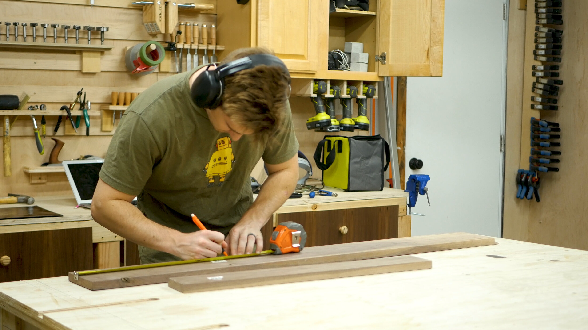
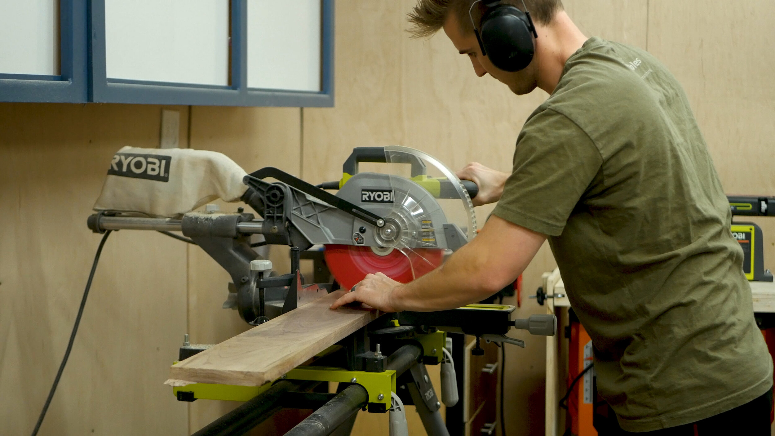
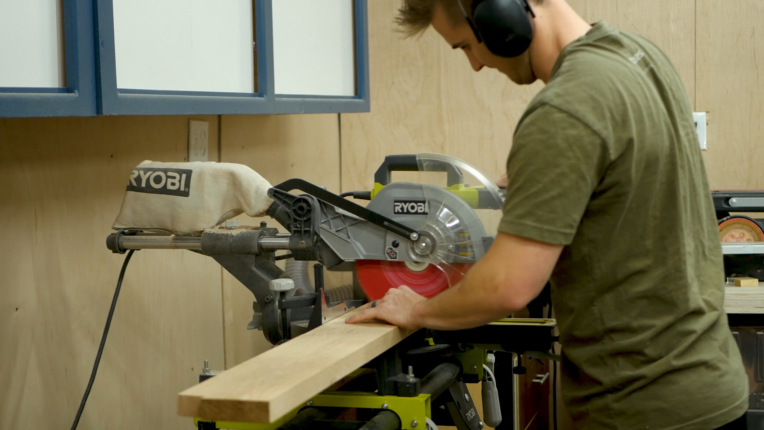
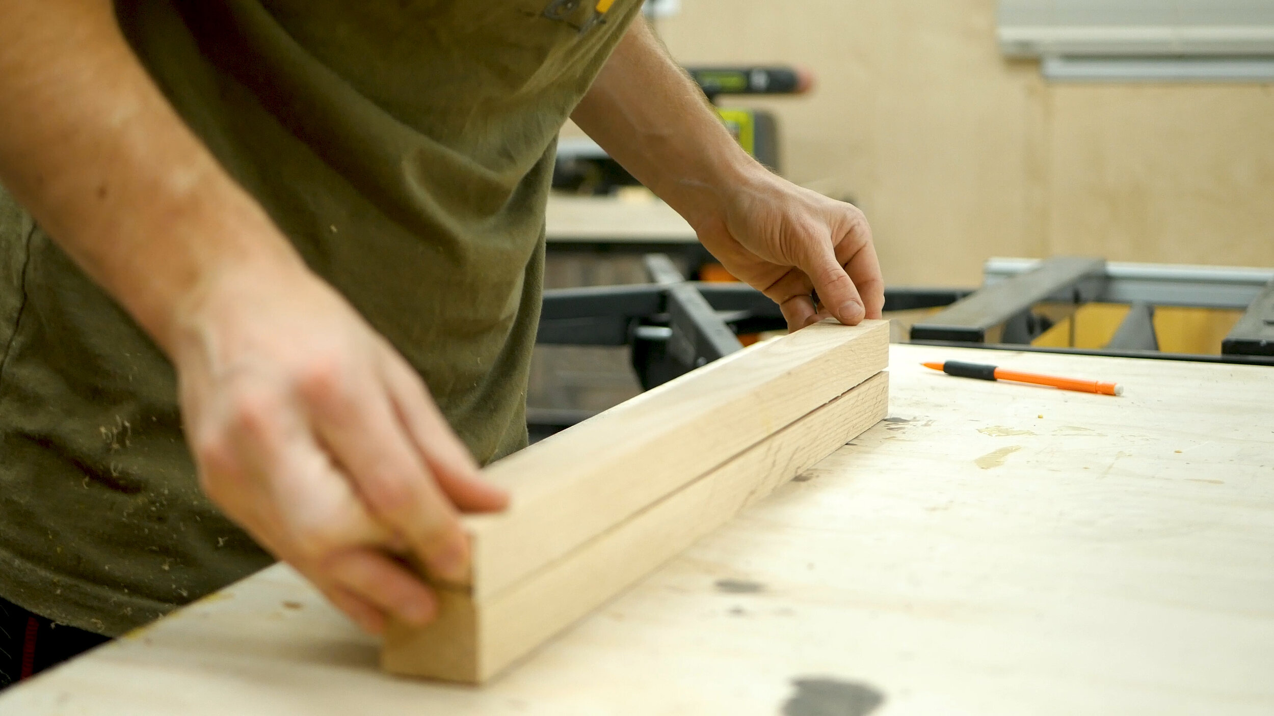
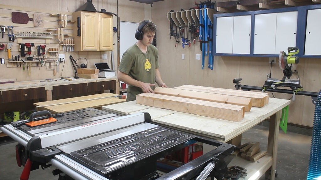
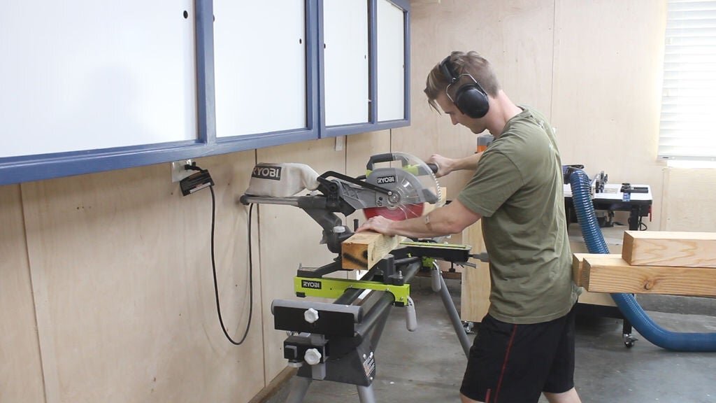
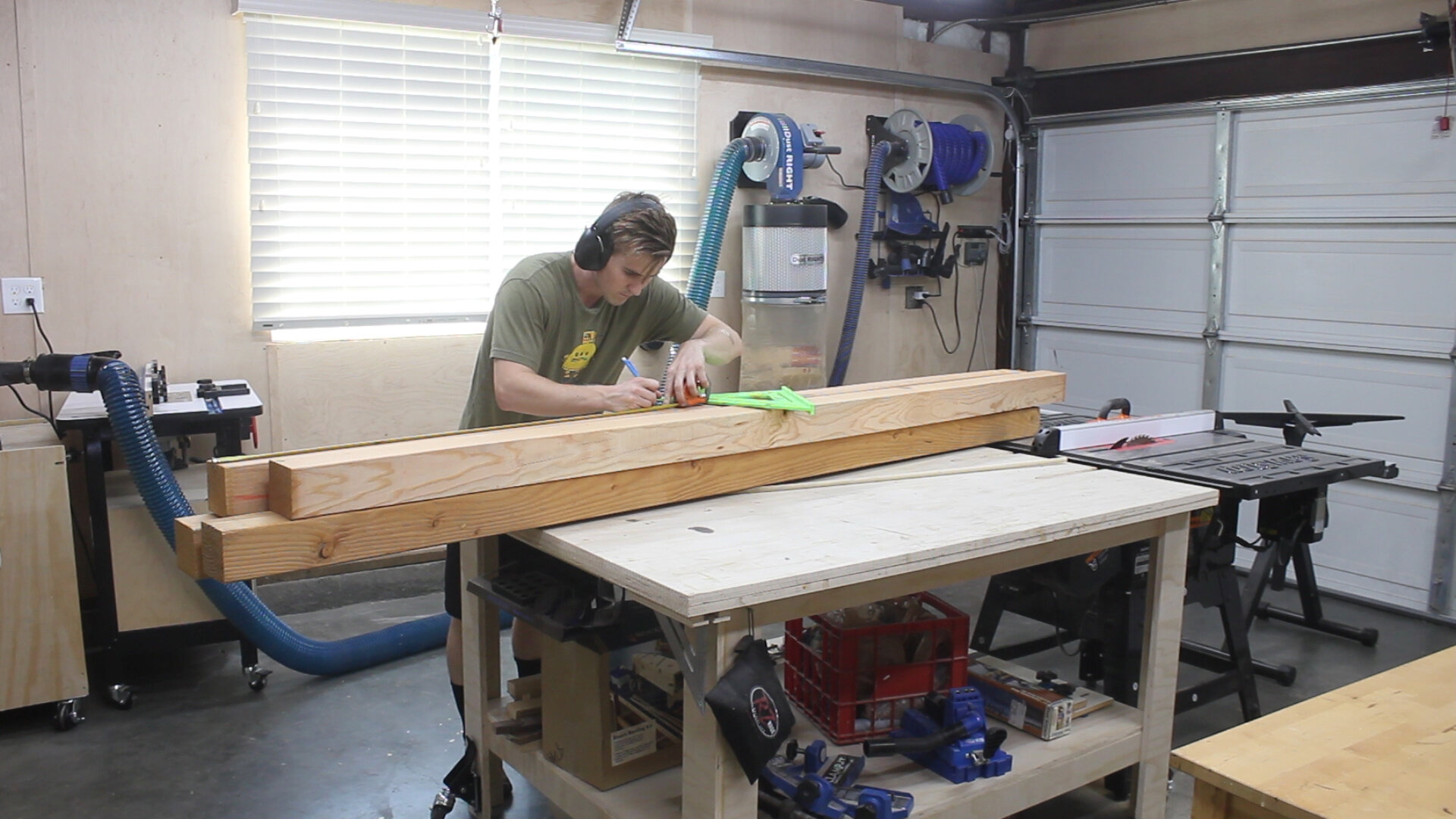
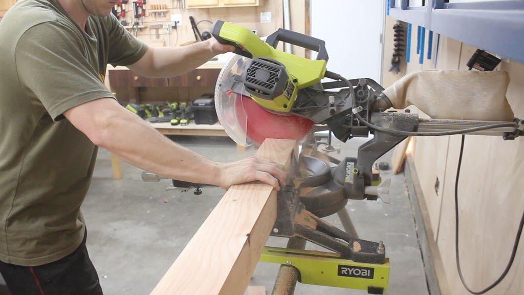
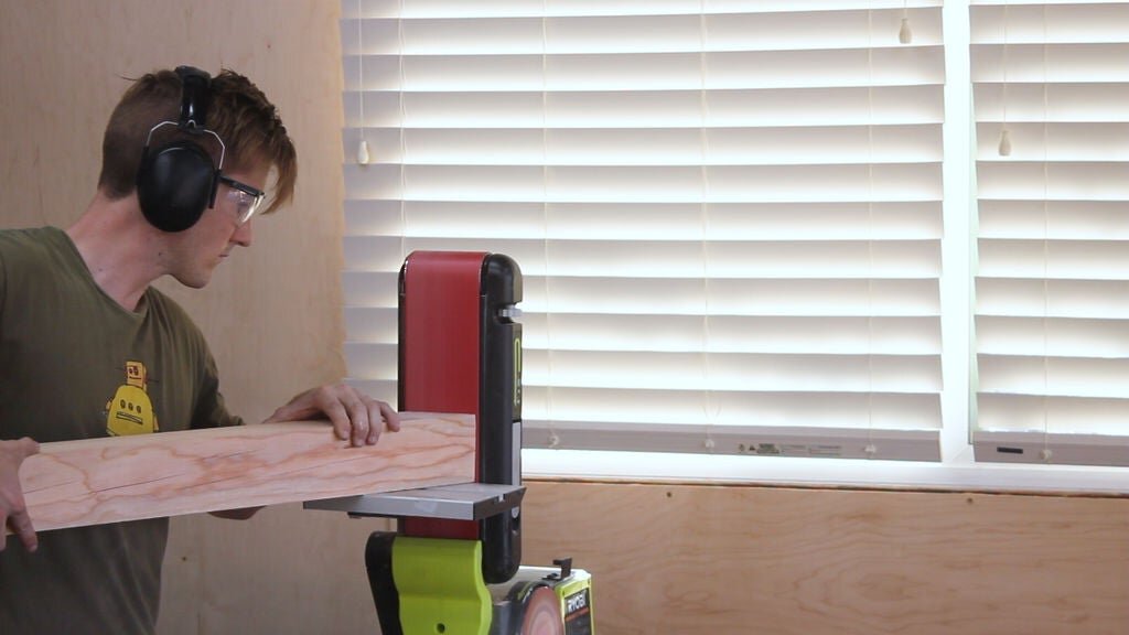
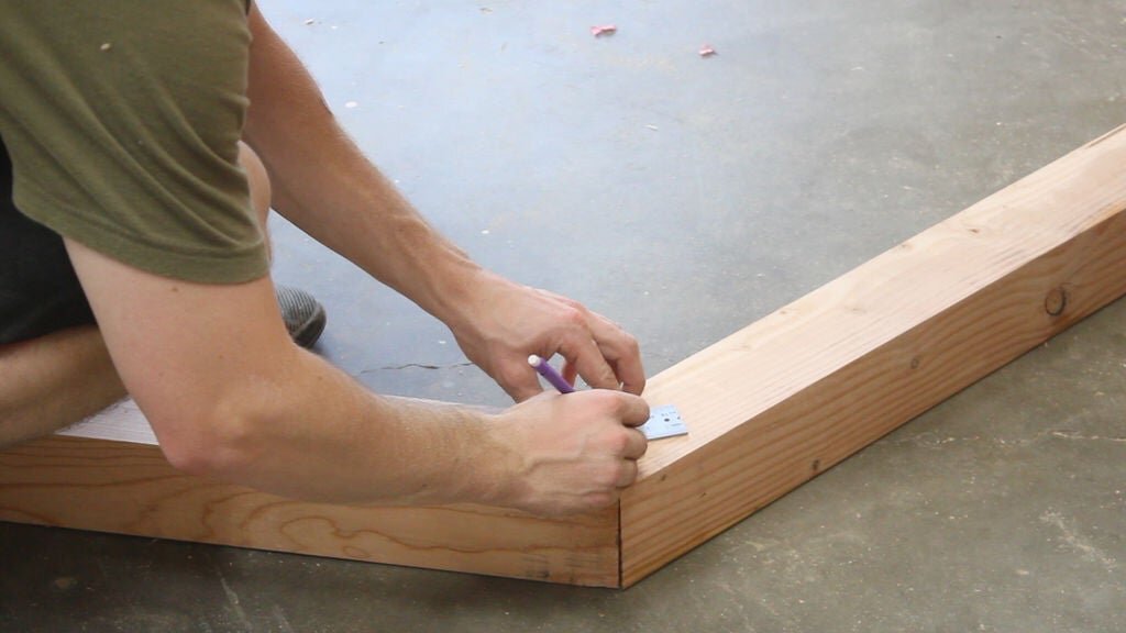
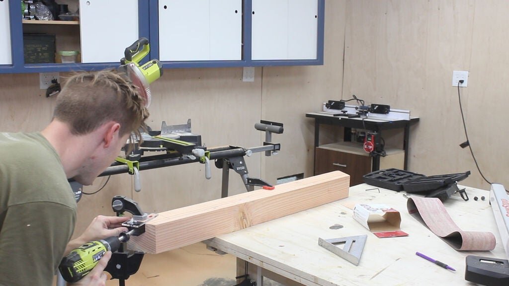
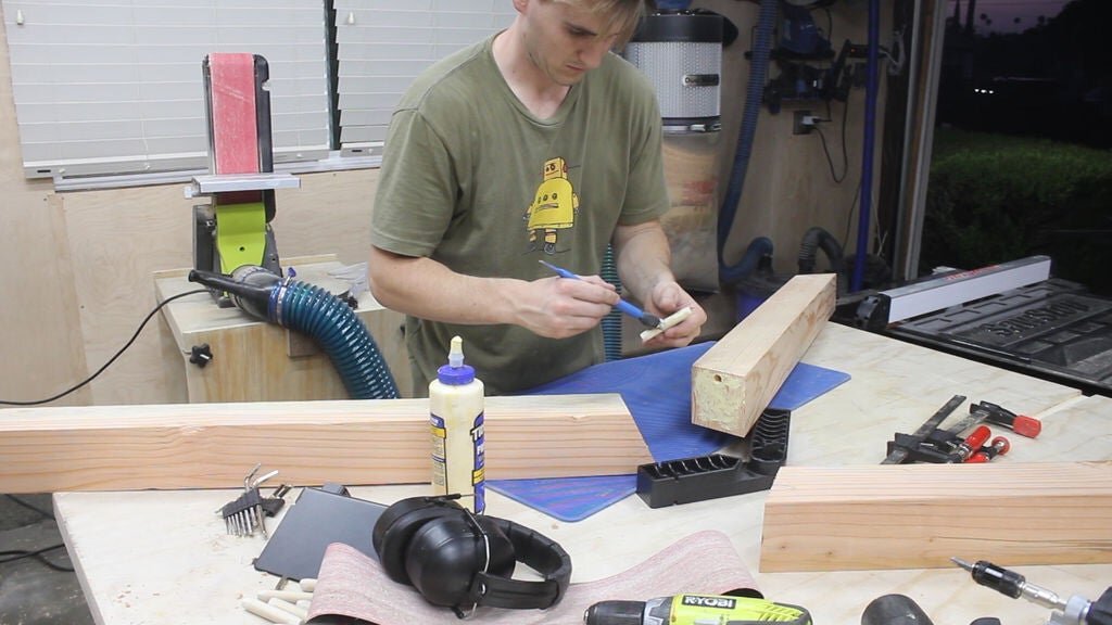
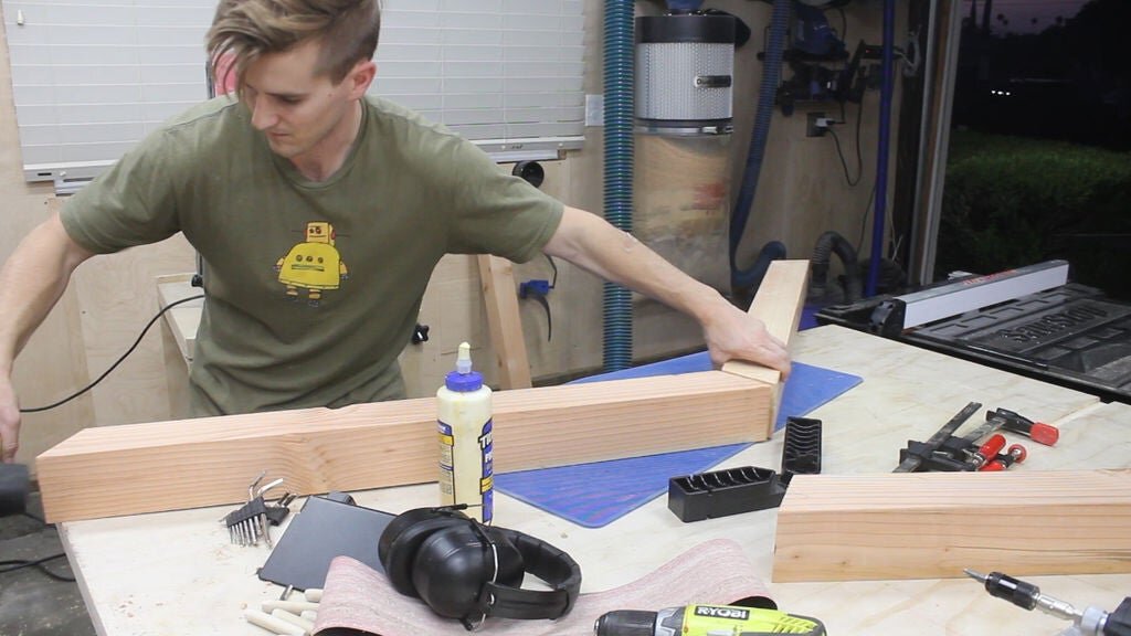
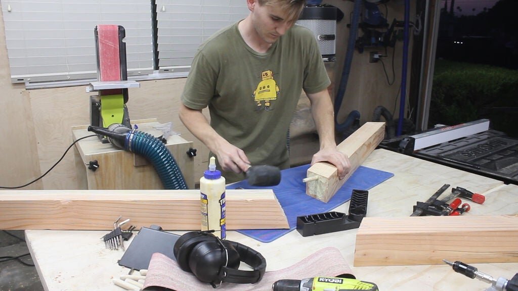
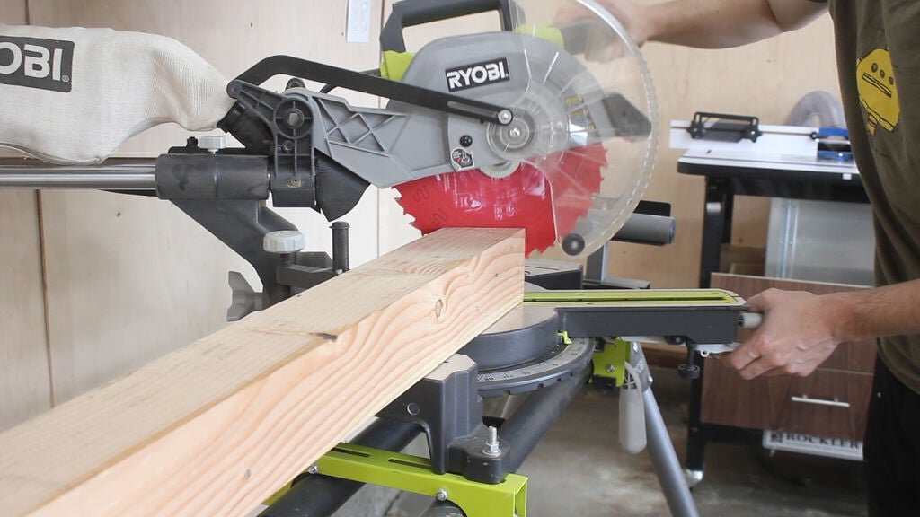
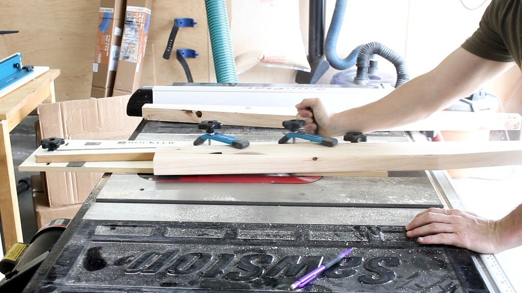
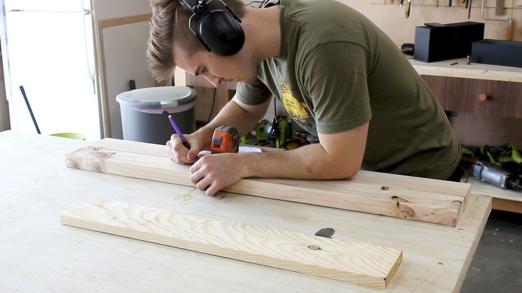
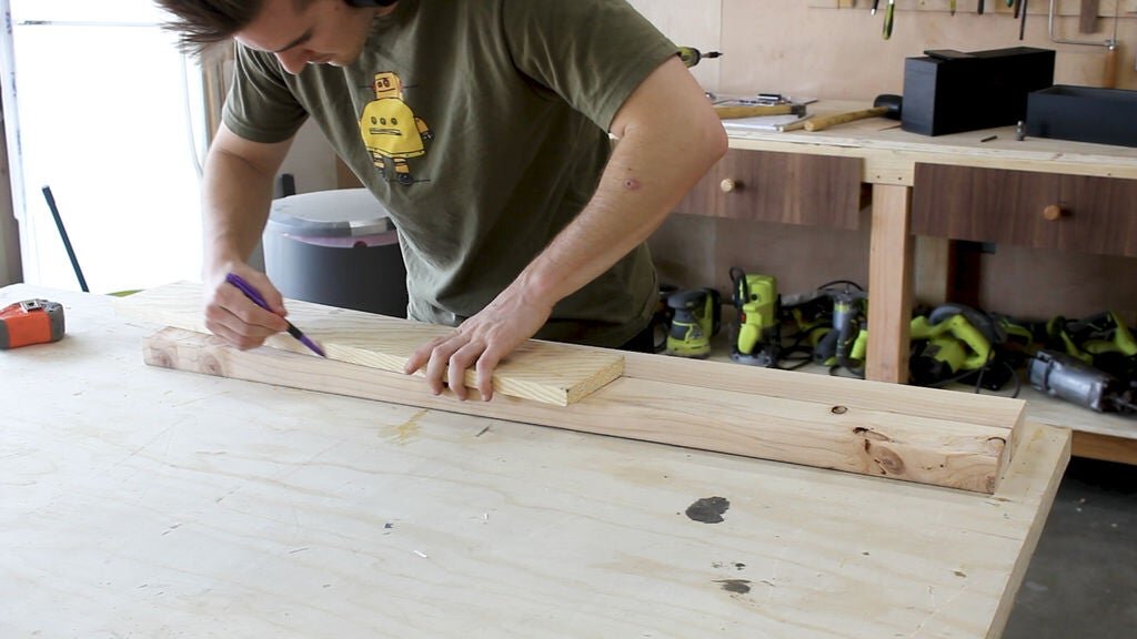
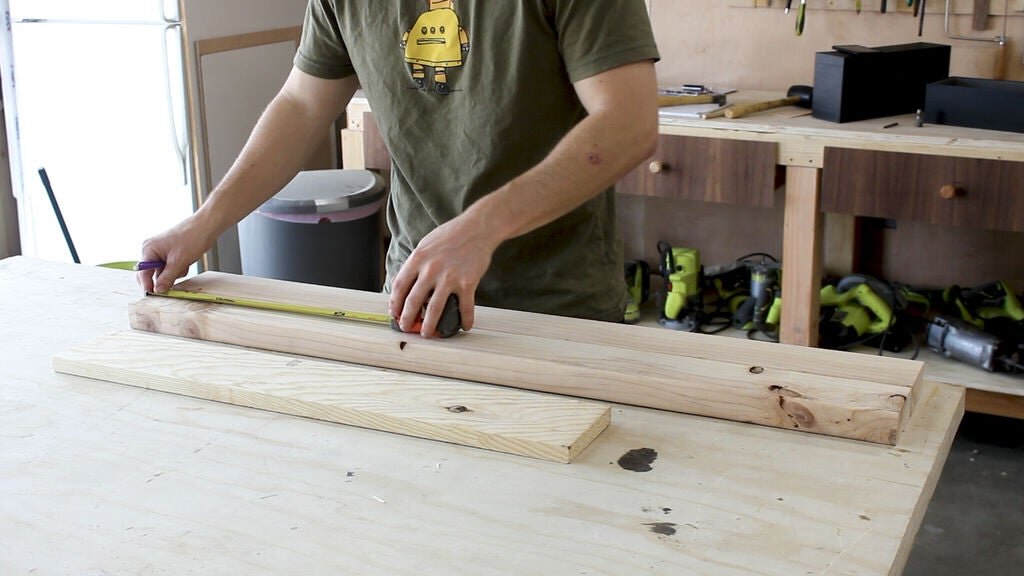
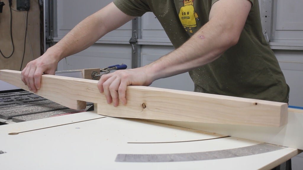
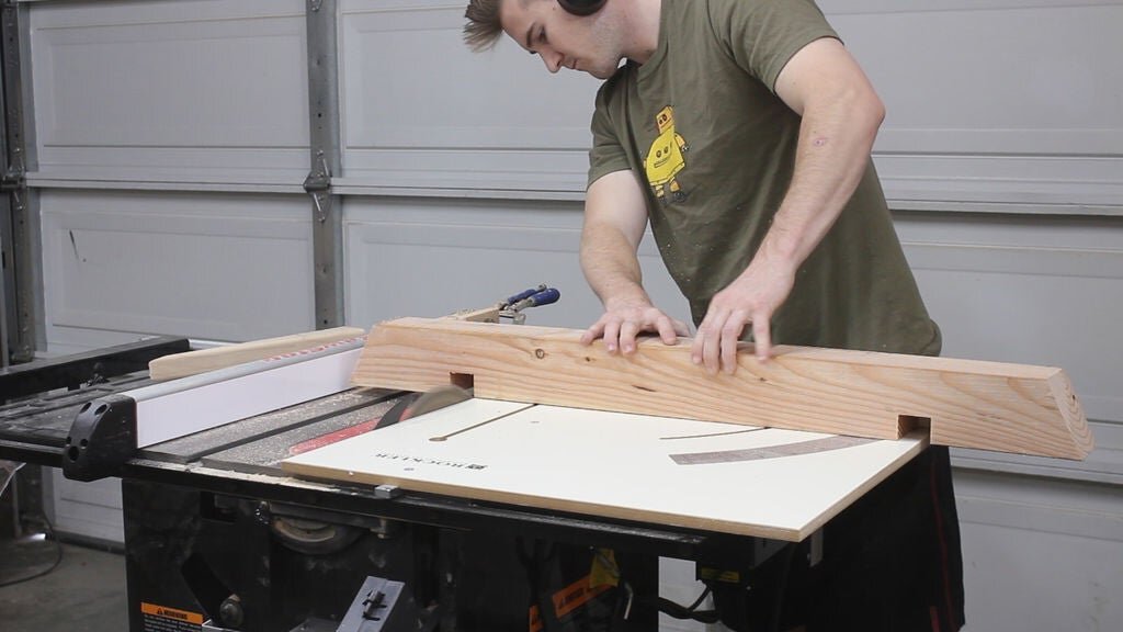
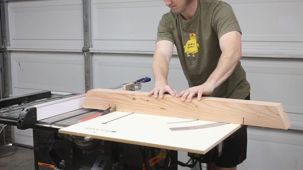
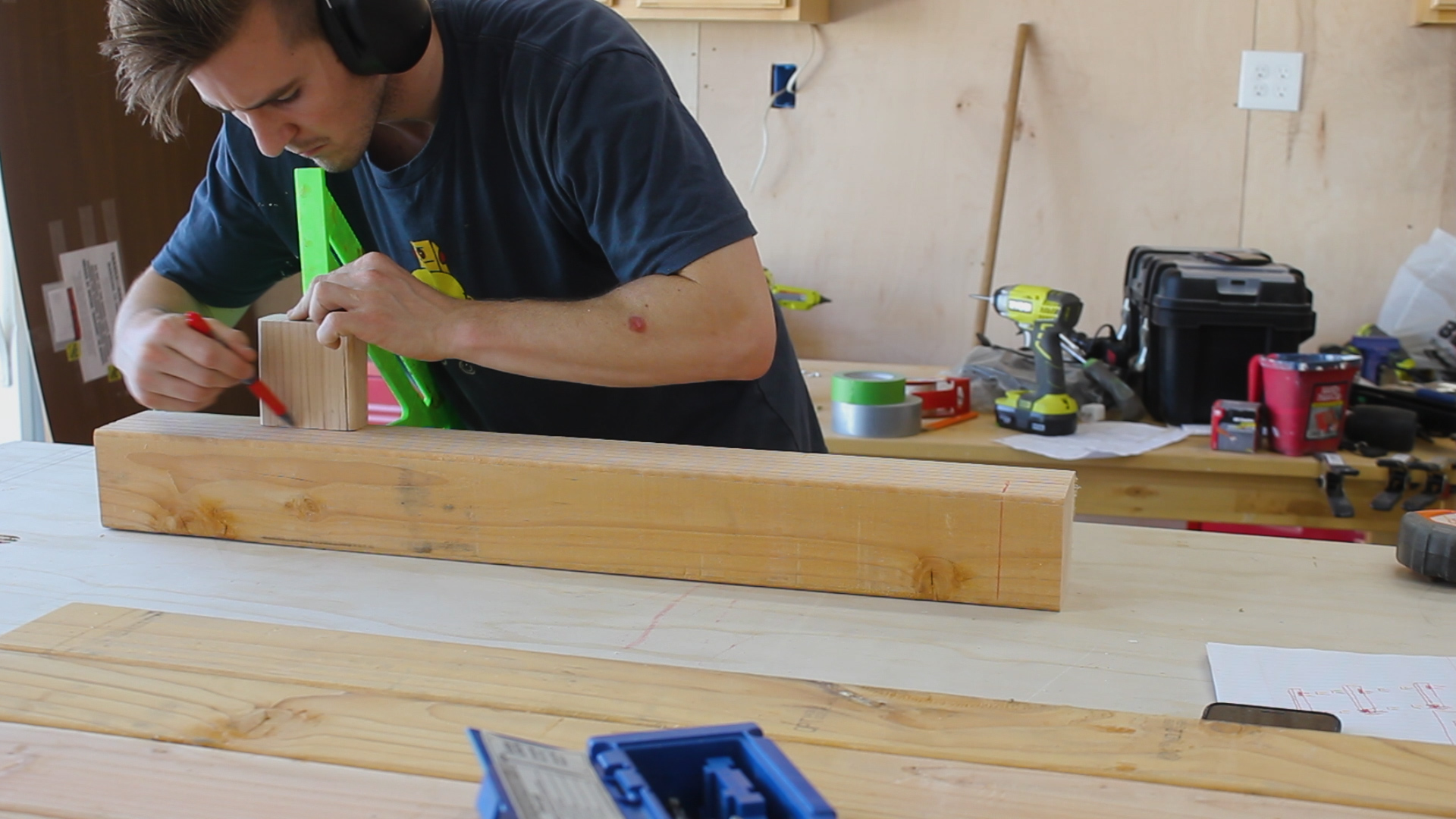
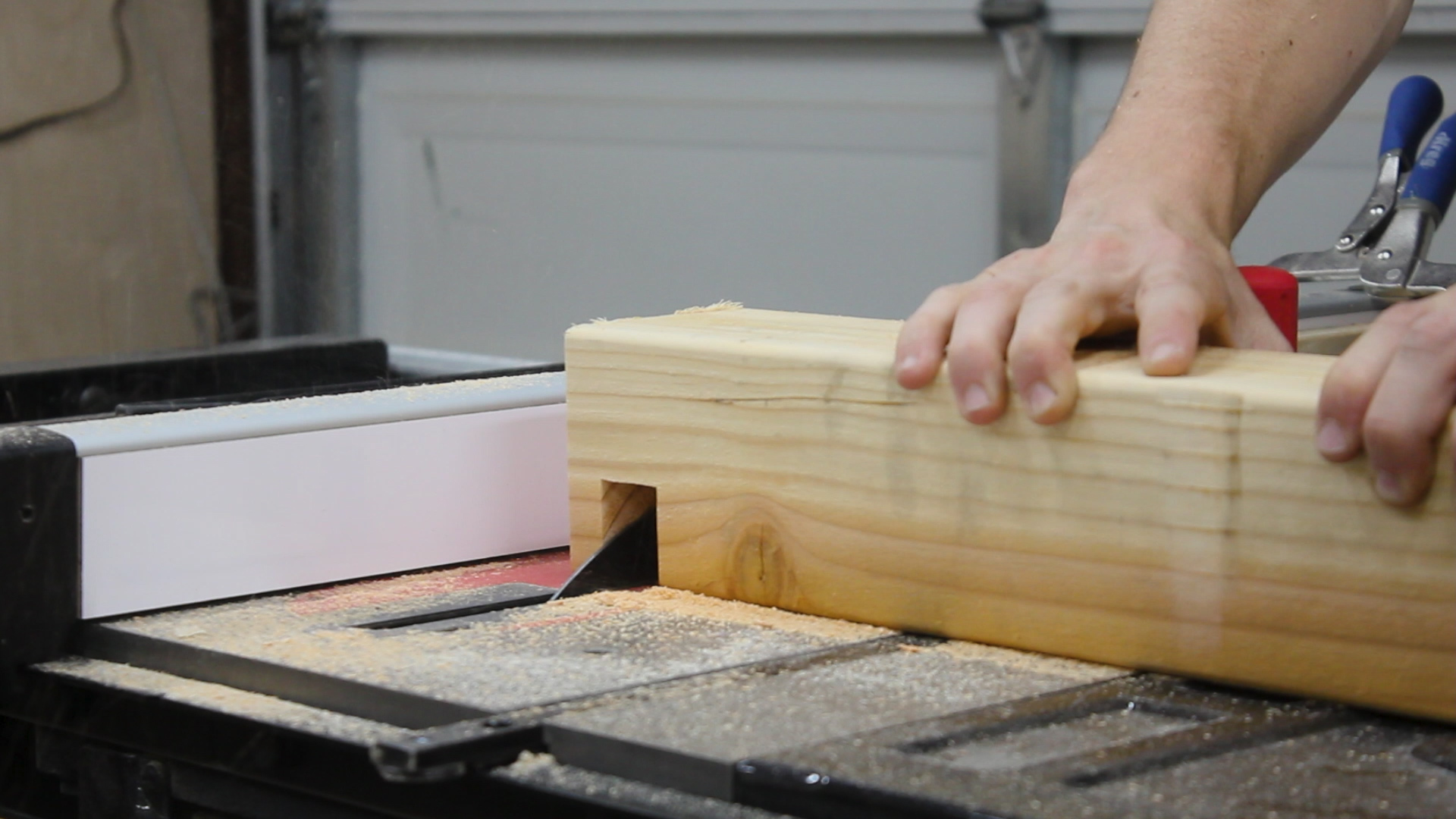
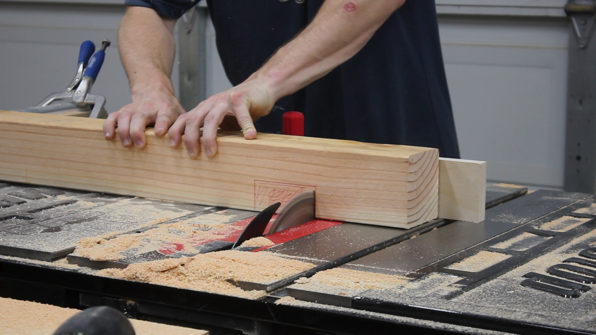
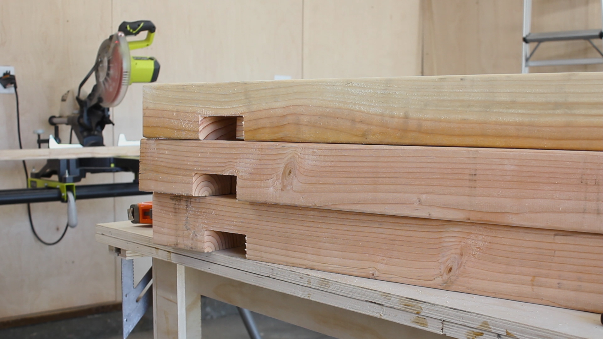
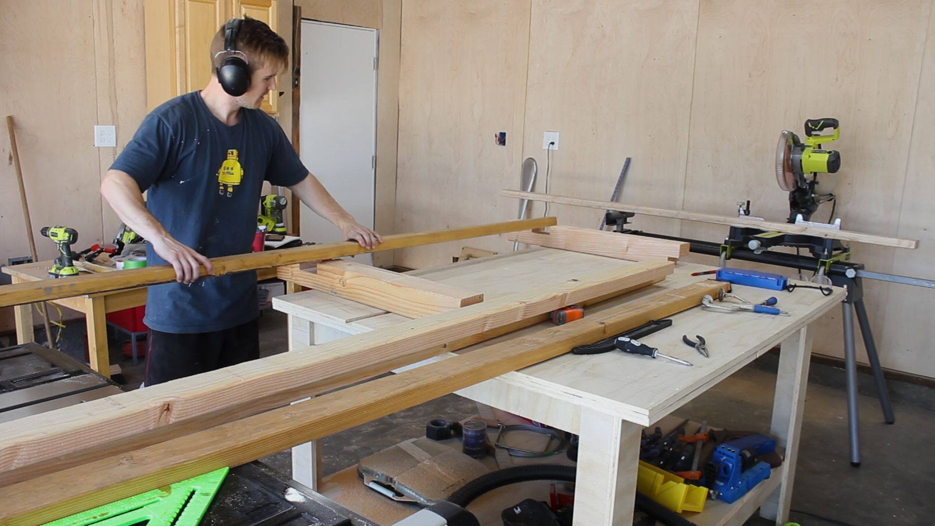
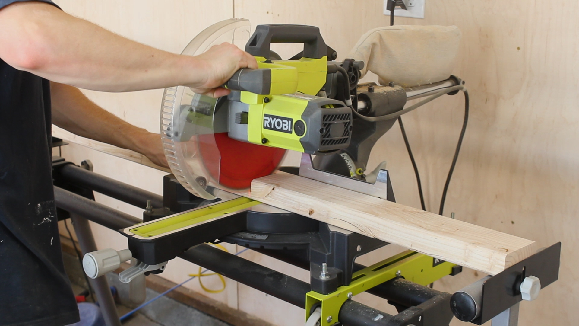
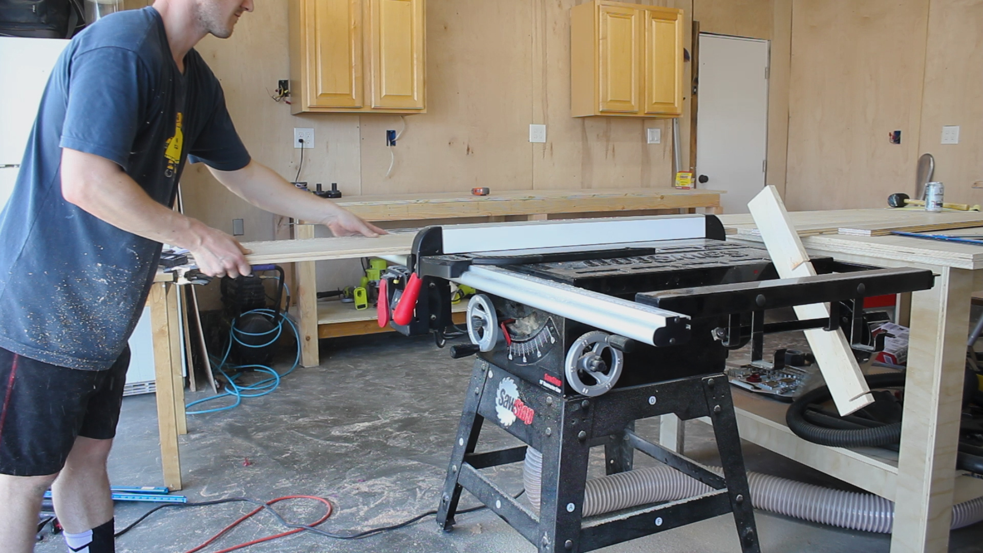
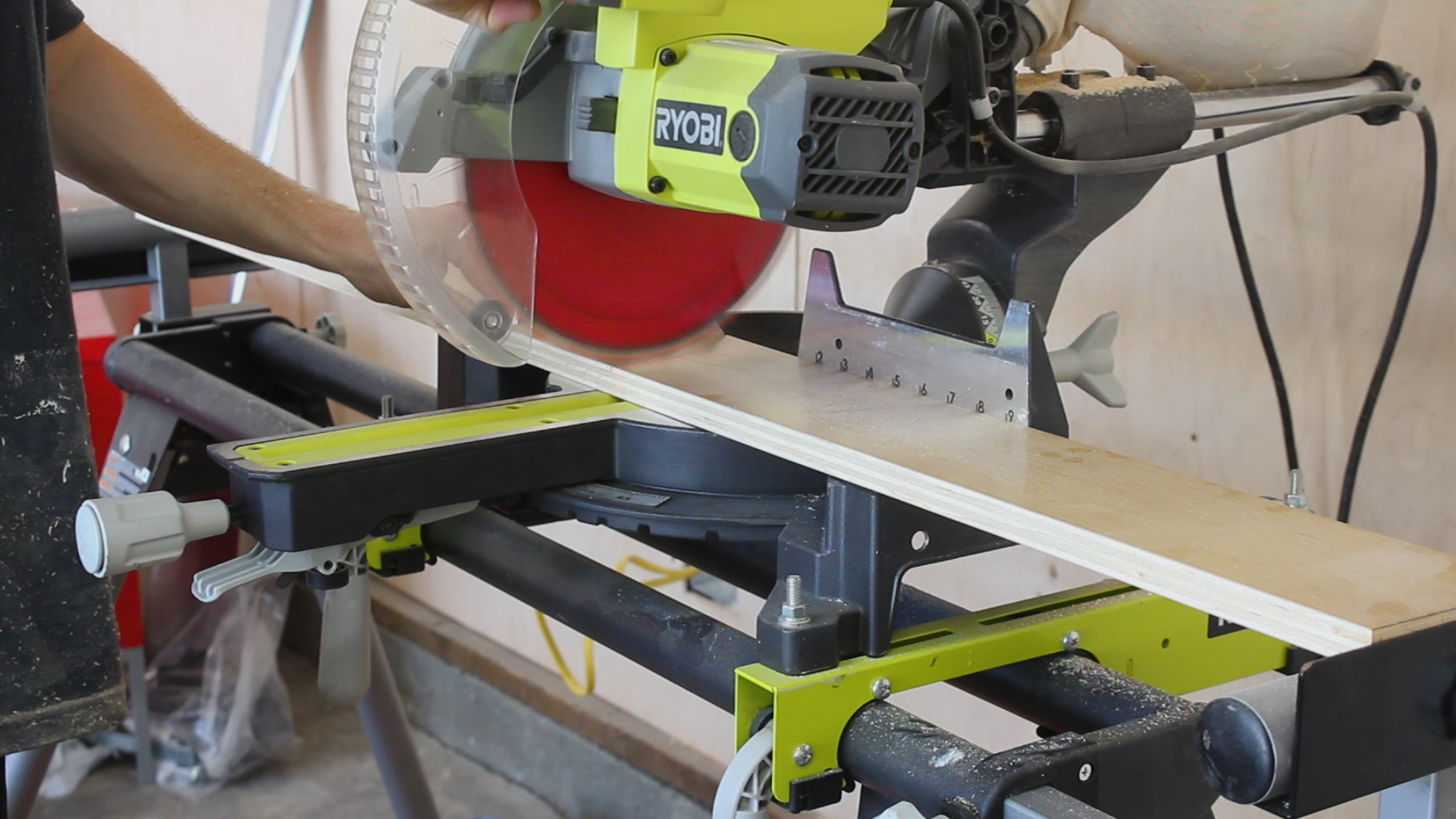
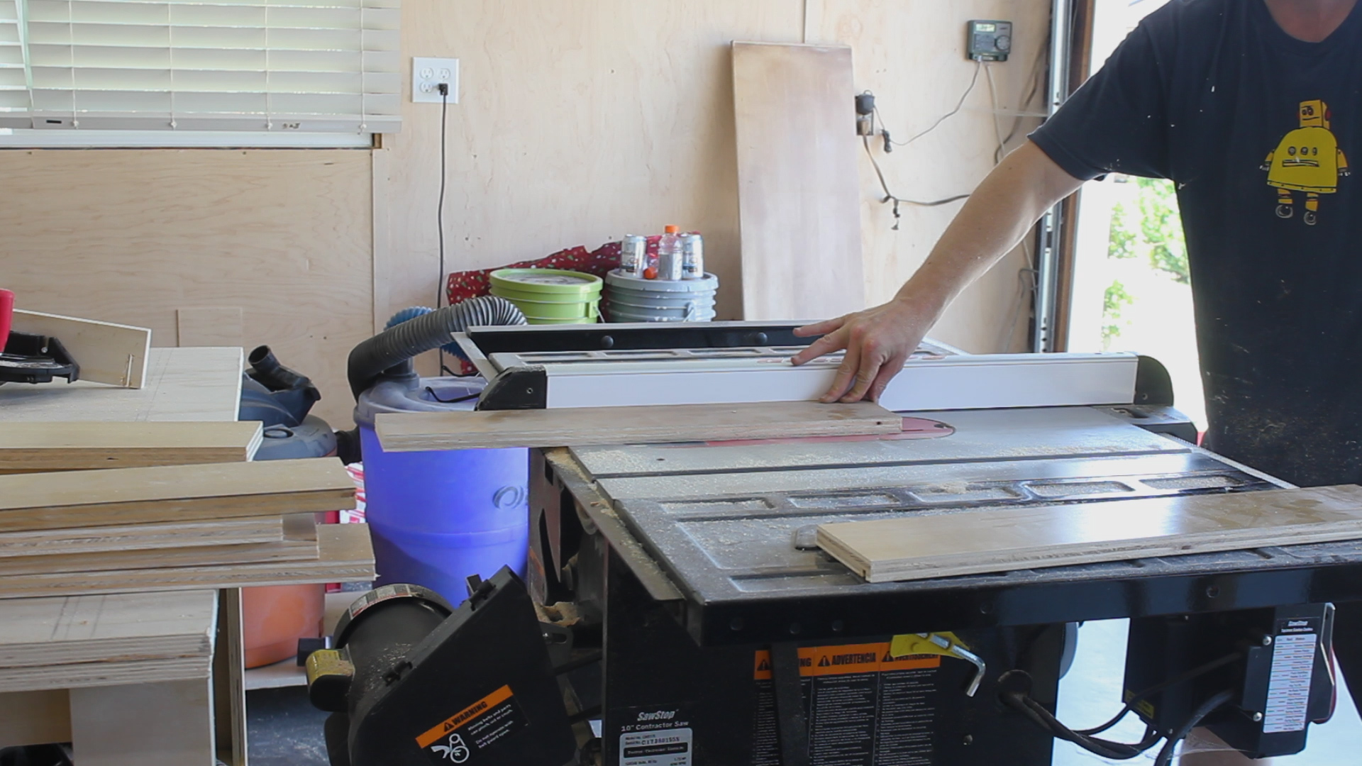
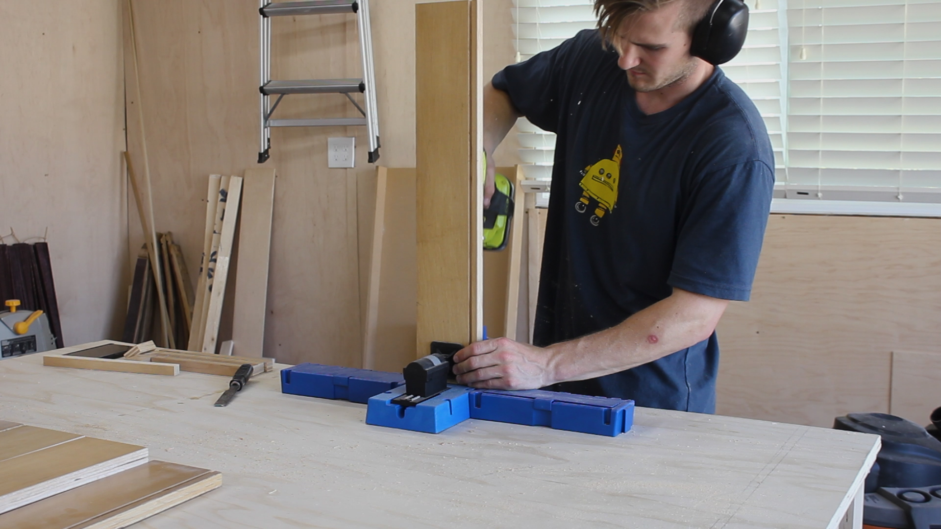
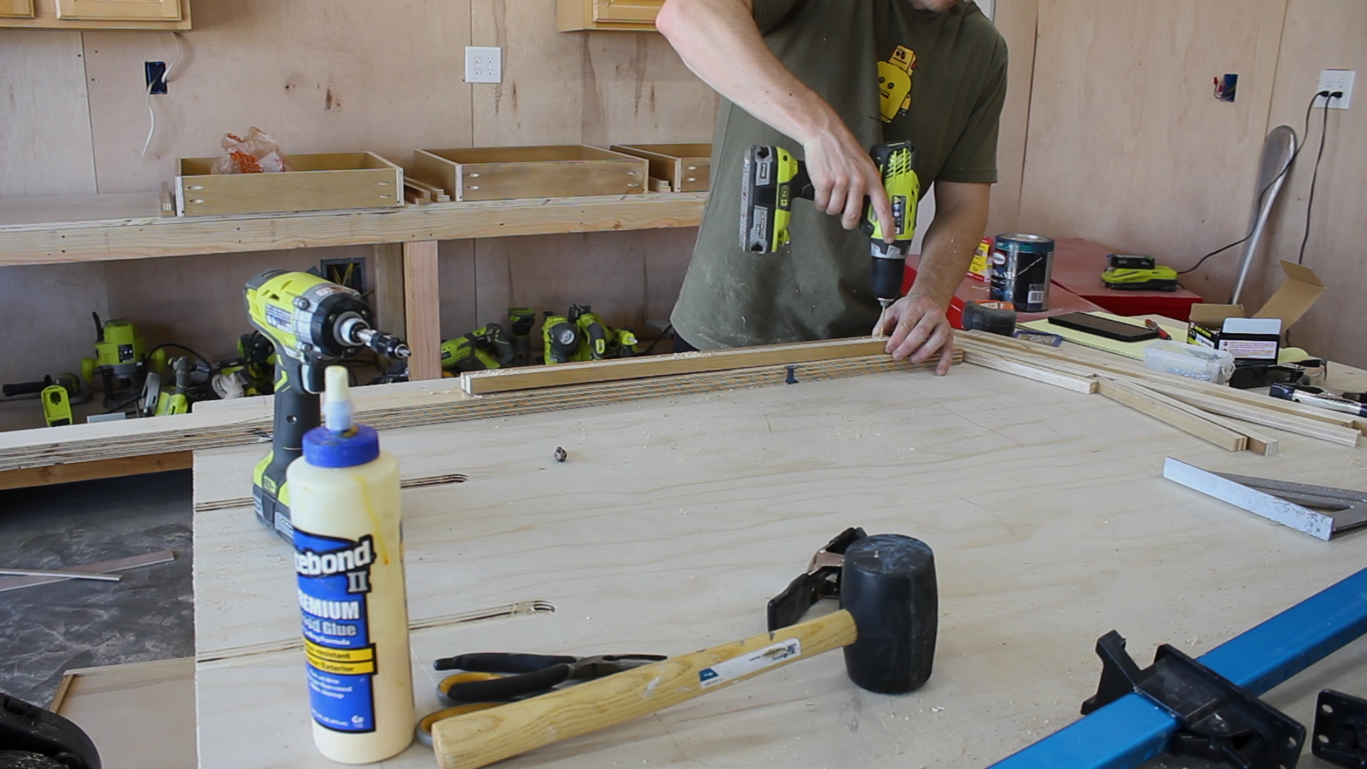
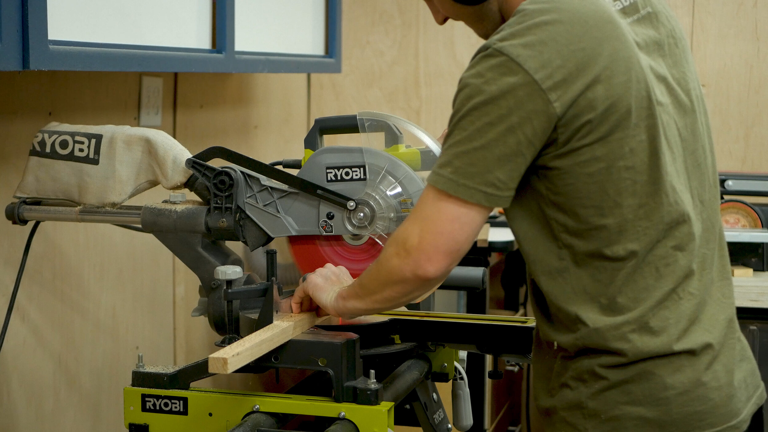
I began the project by marking out and cutting my 4/4 walnut to length. The project didn’t need much - just enough to properly stack and laminate together to form the broom portion (Pics 1-3).

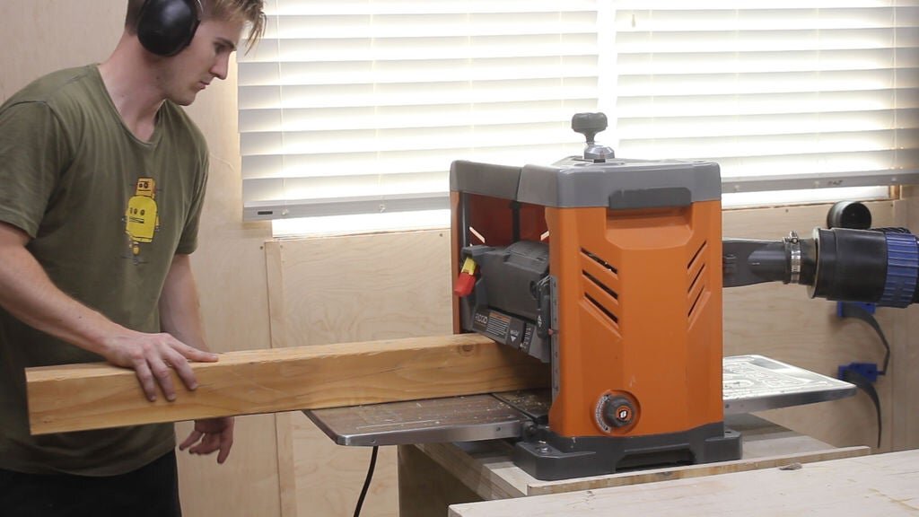
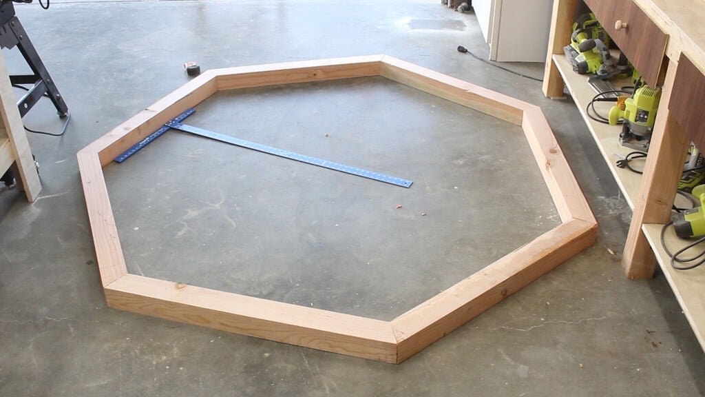
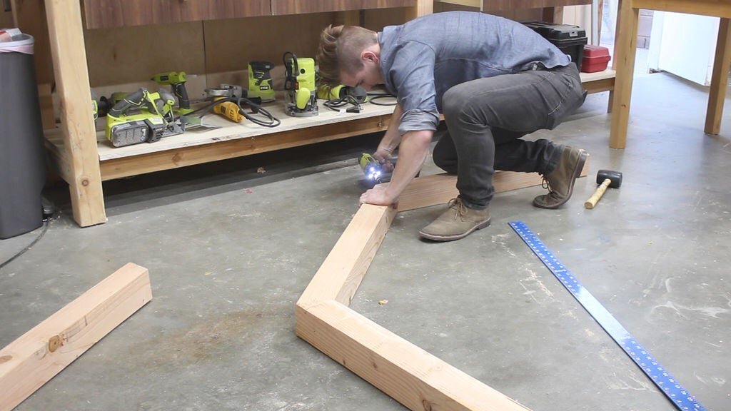
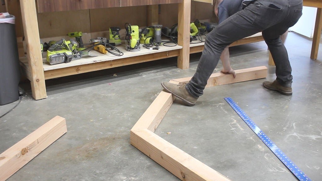
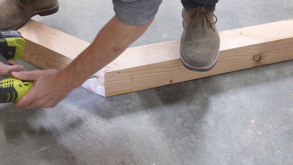
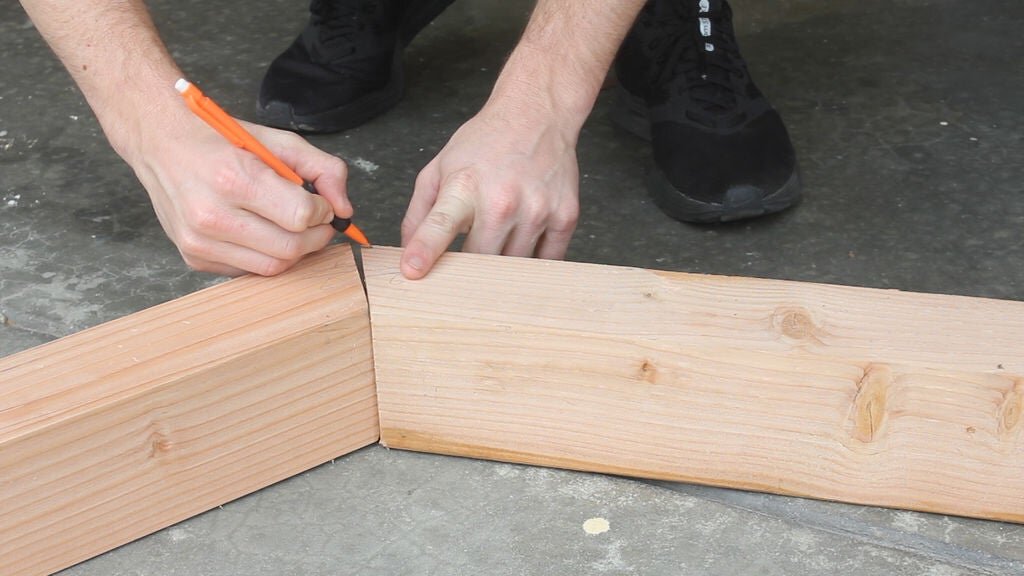
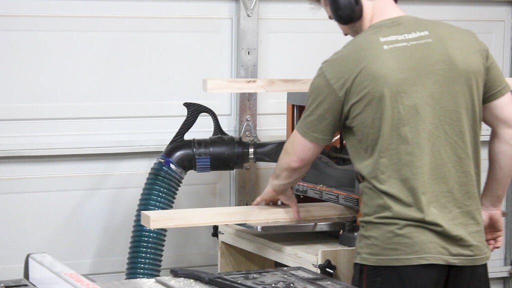
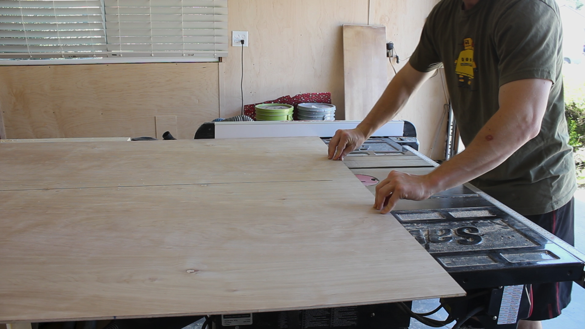
The next step, in similar fashion, was to cut down the white oak I had to length and with and then laminate together. The reason you need two pieces laminated together is because the broom handle is very curved in design, so you’ll need more wood to build that out when powercarving (Pics 4-6).

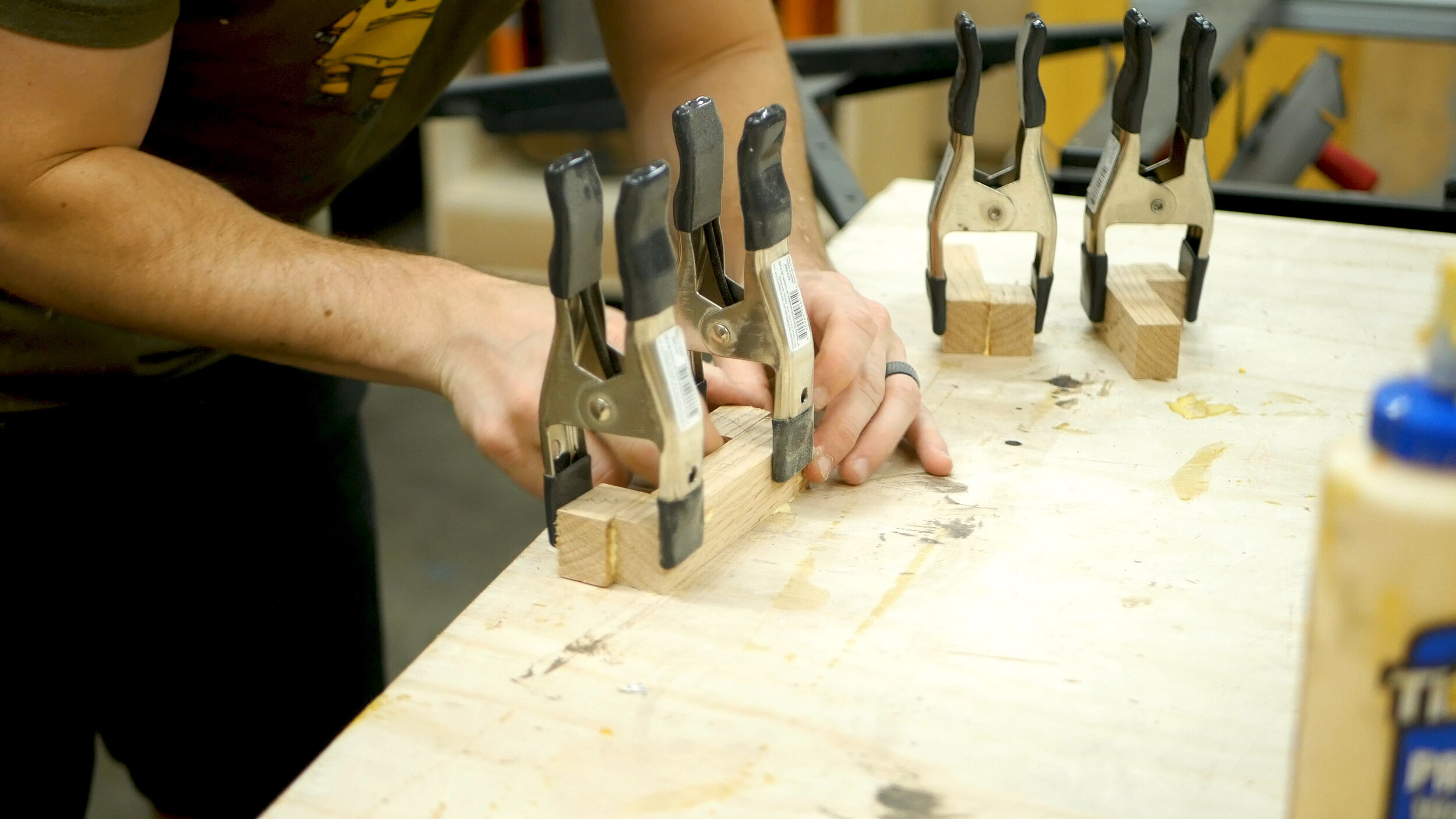
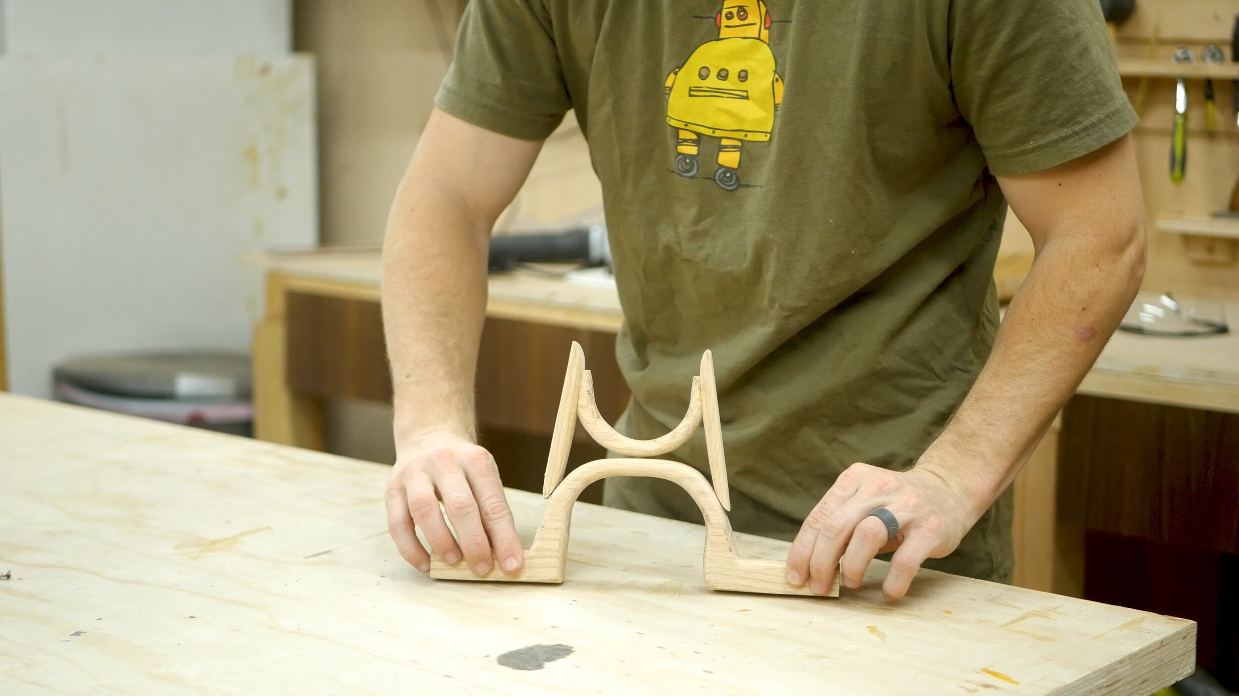
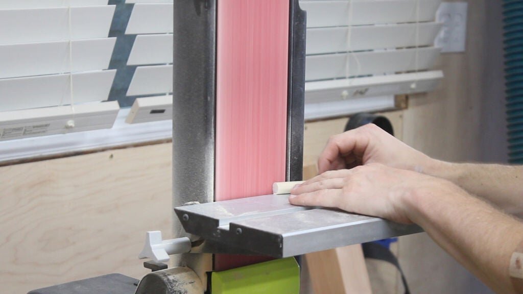
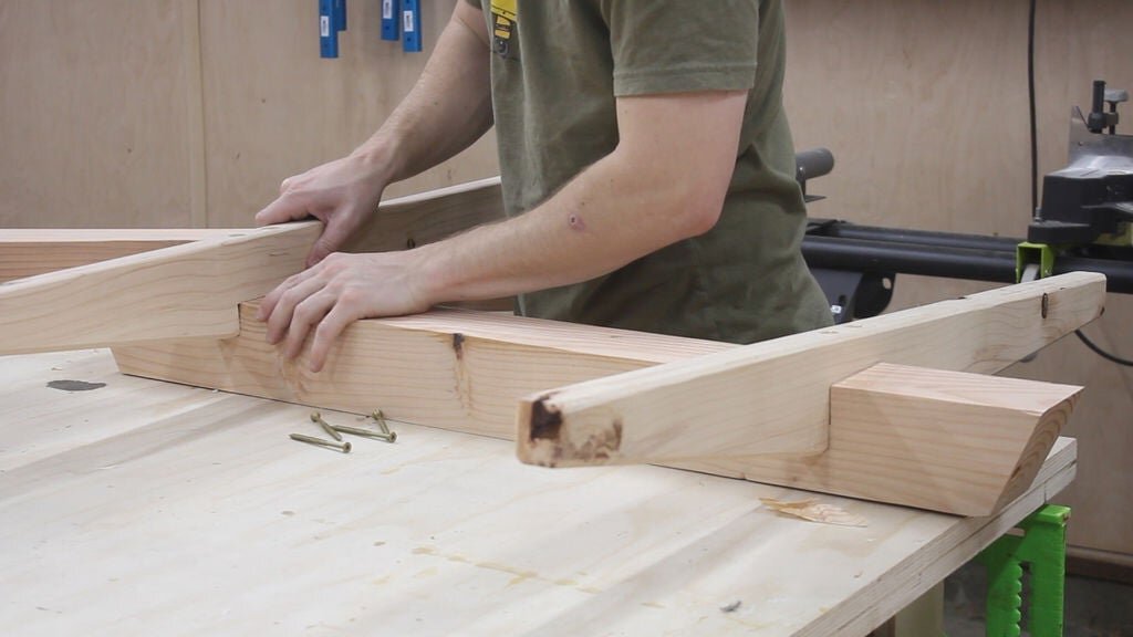
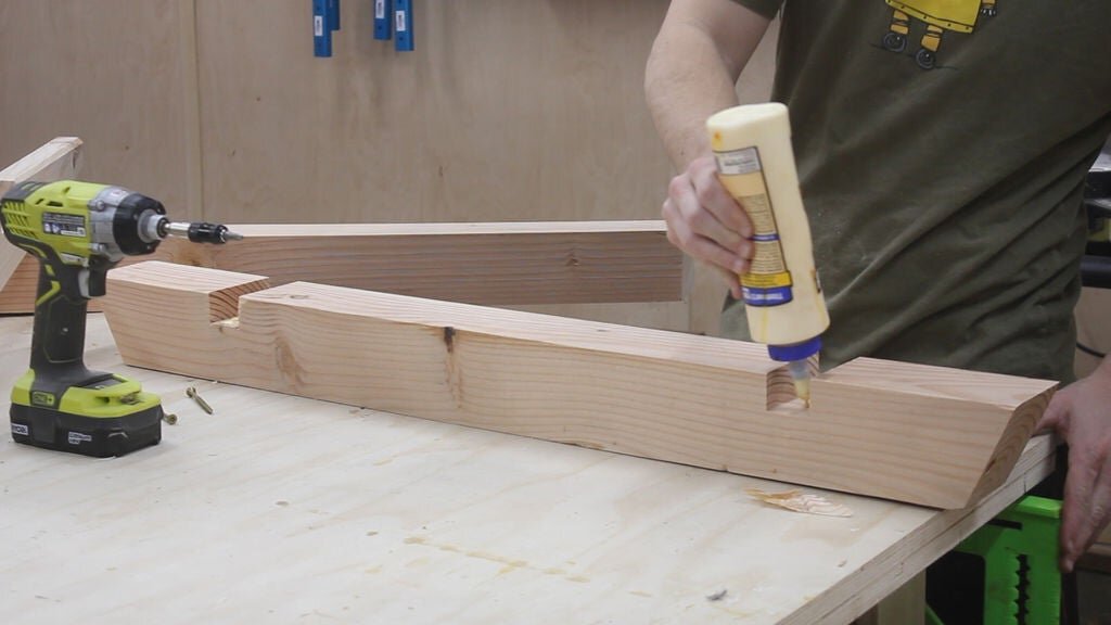
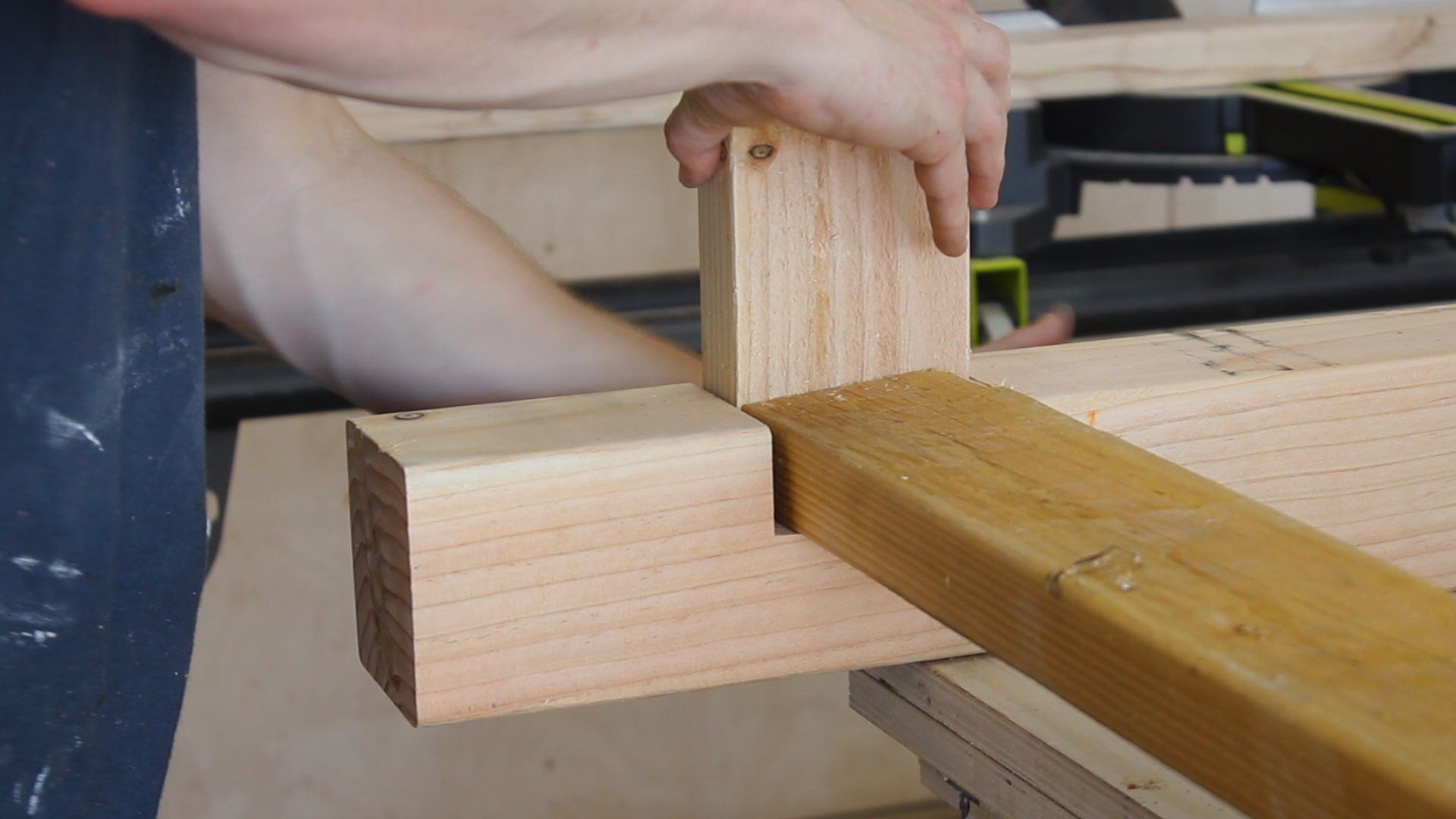
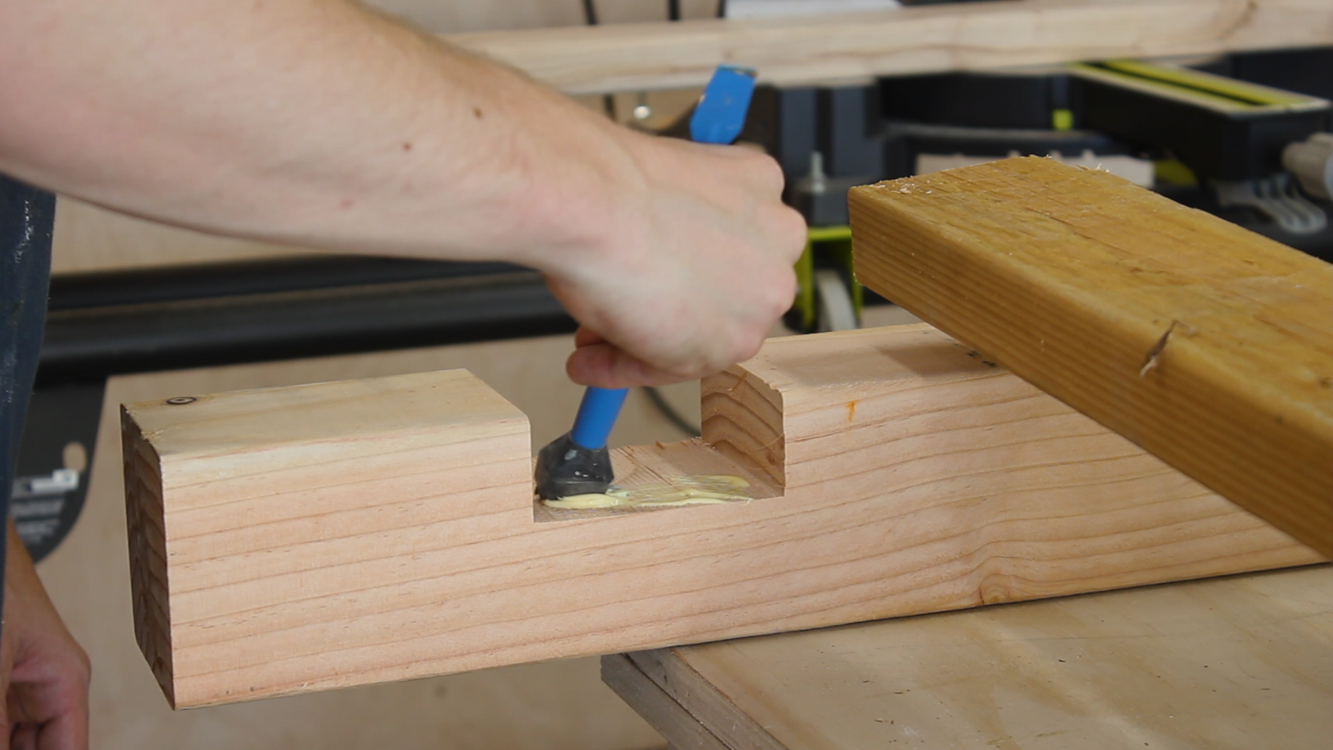
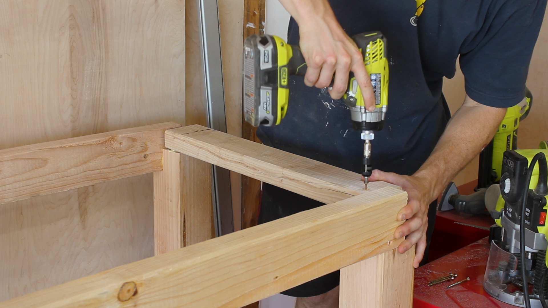
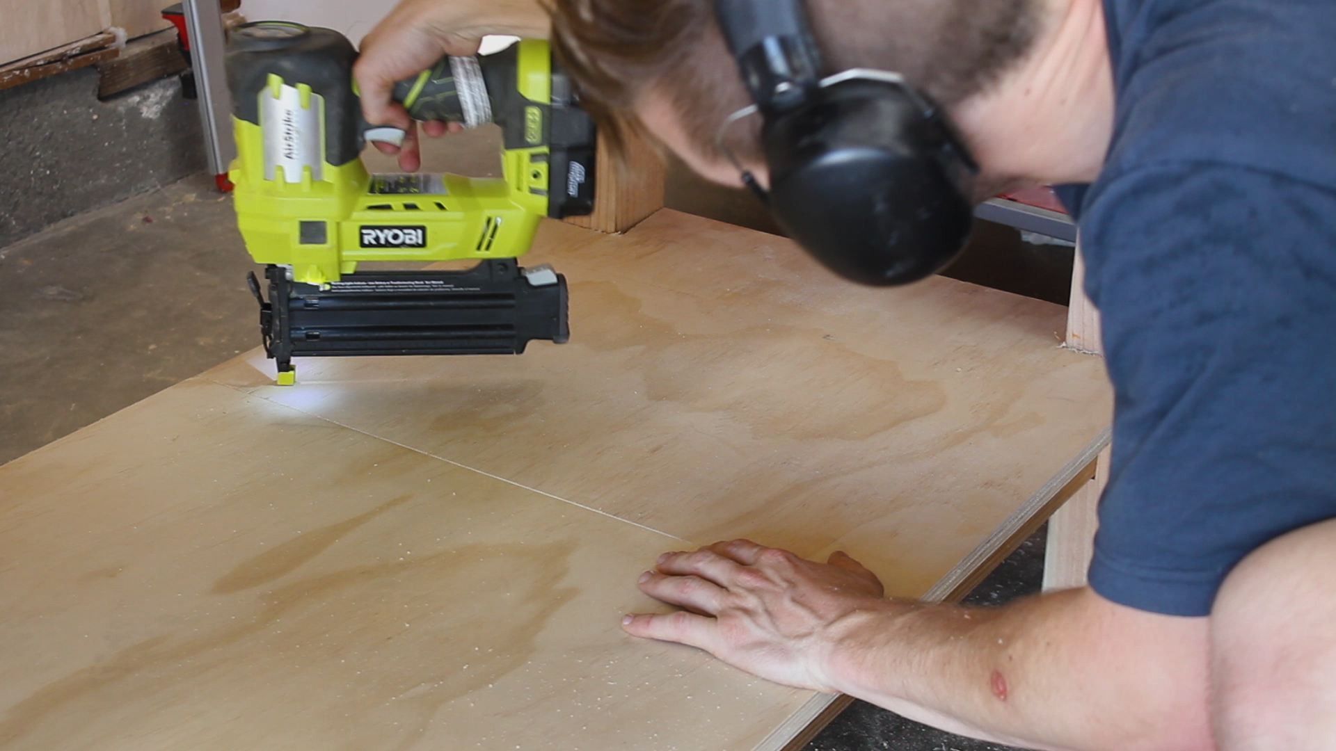
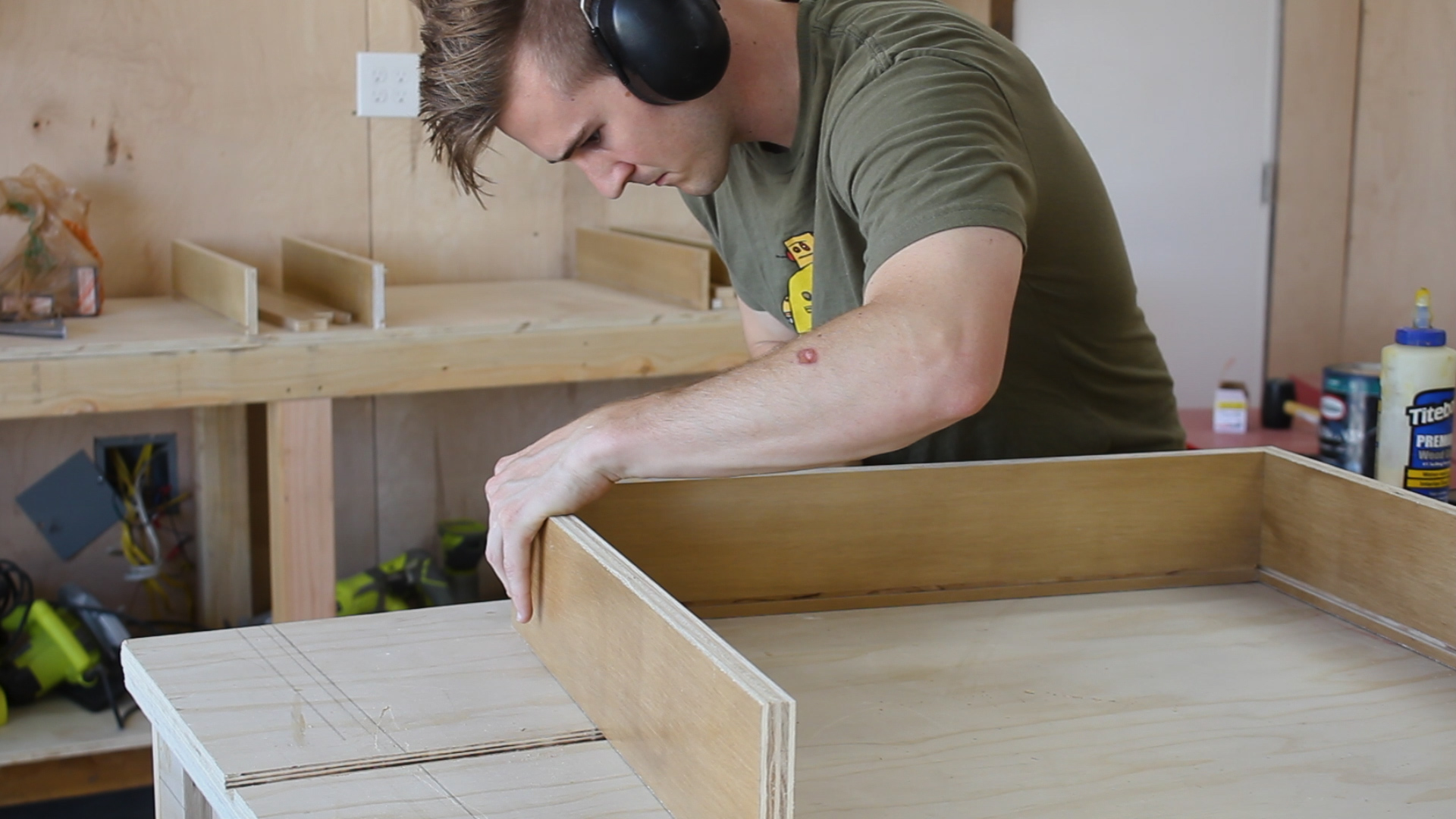
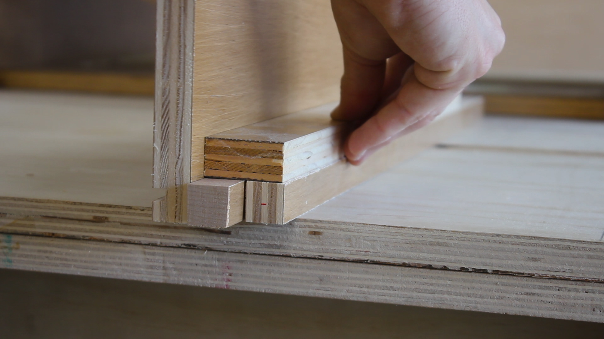
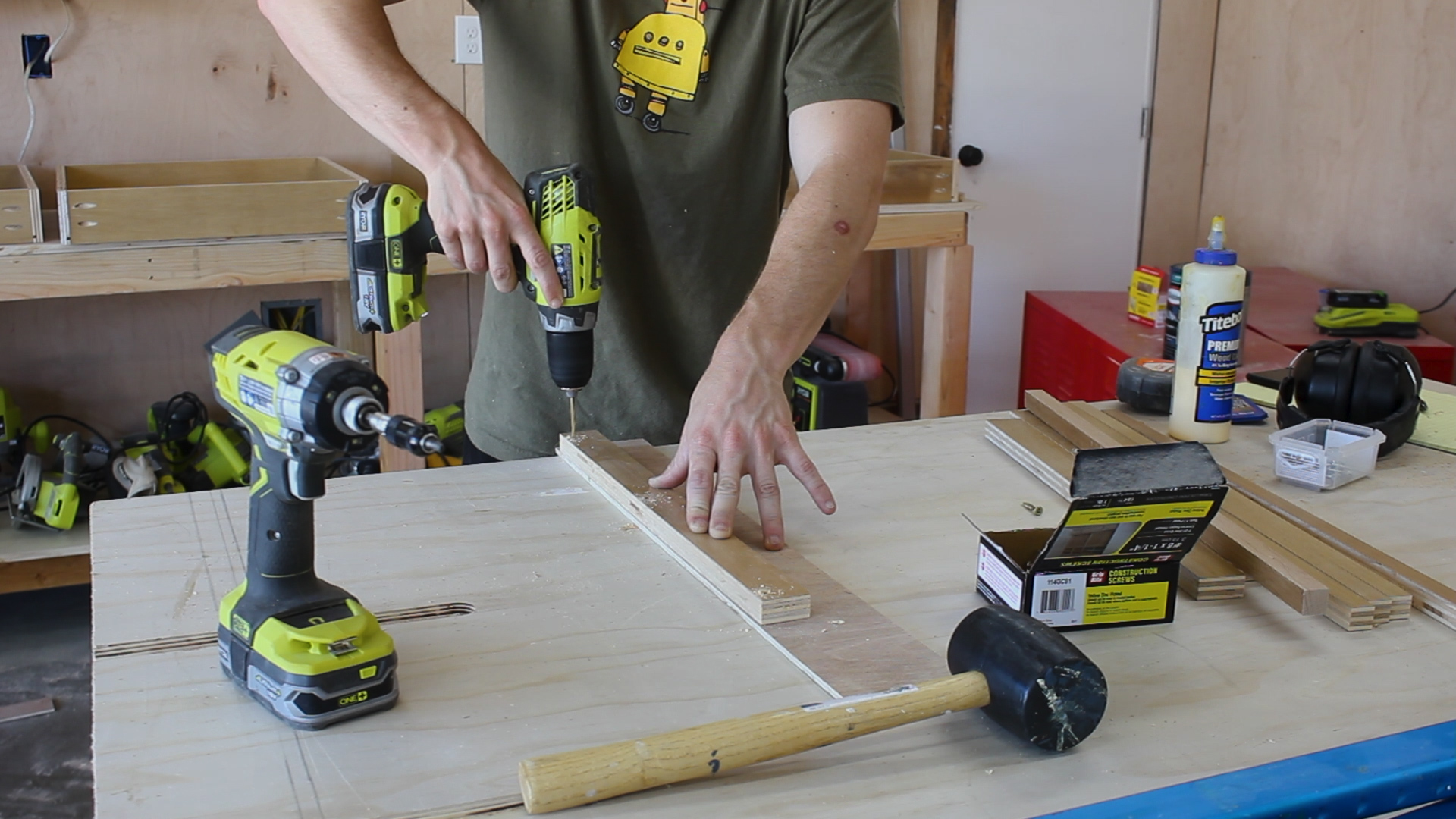
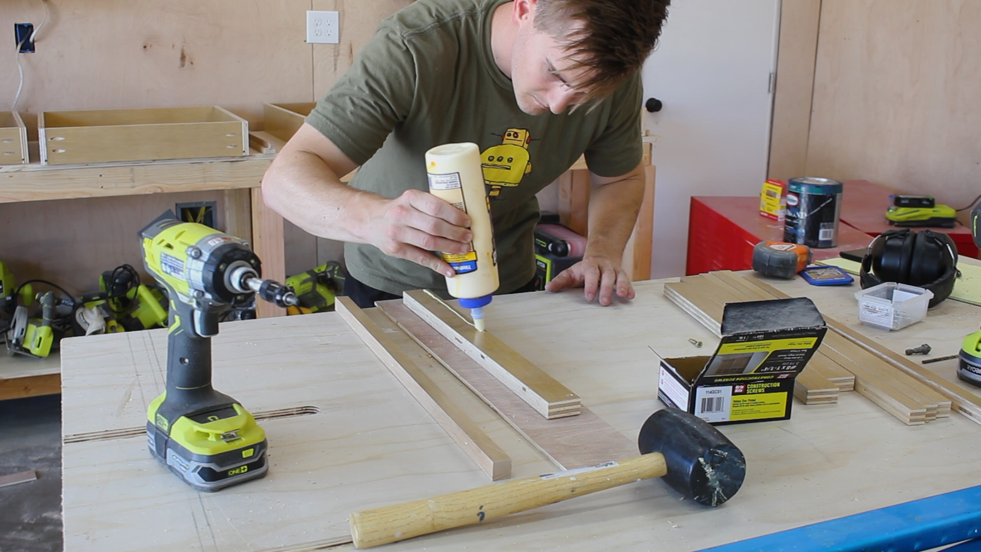
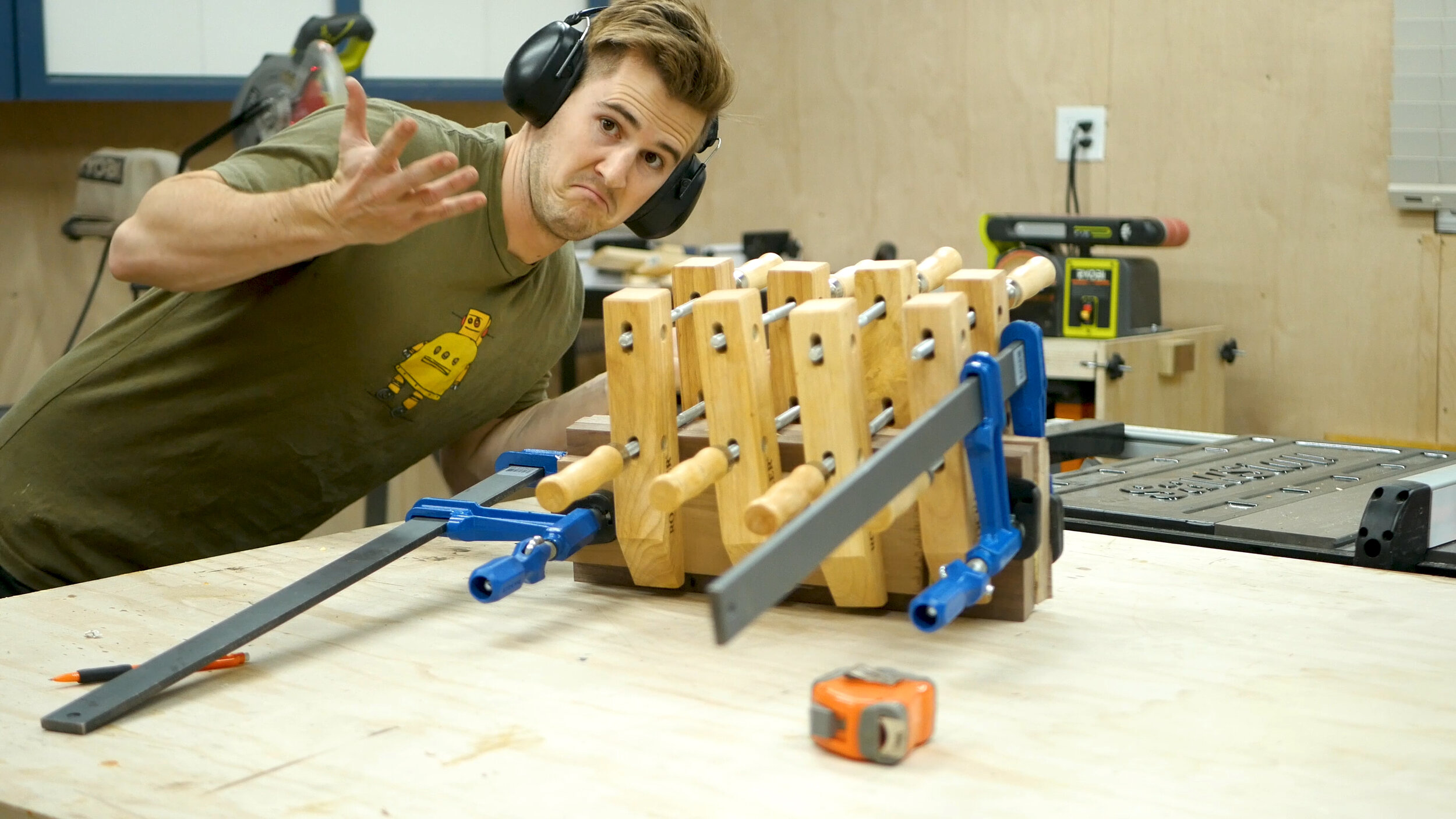
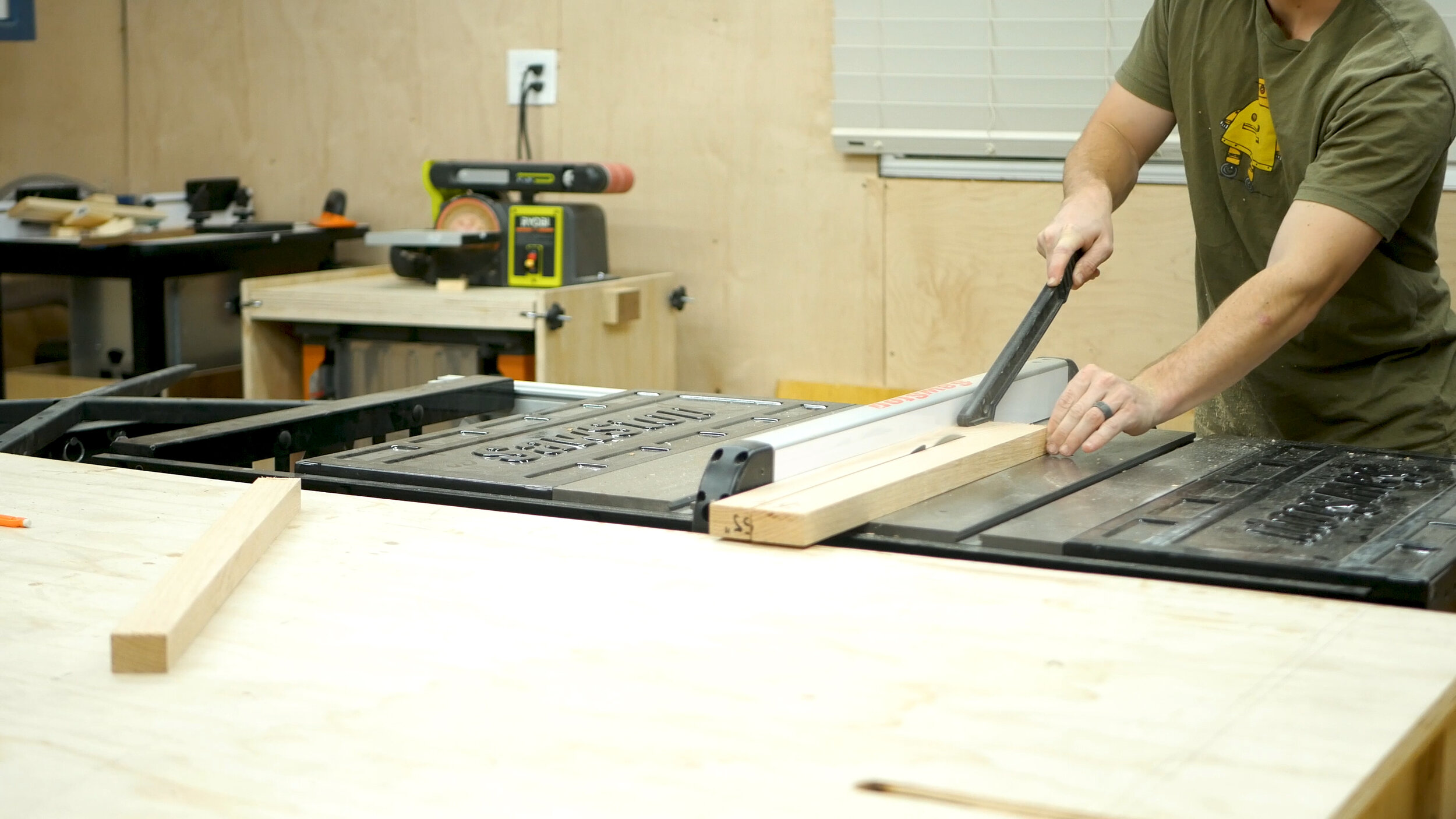
While the glue dried, the next step was to take the remaining white oak and cut down to a series of smaller strips - these were to be used to stack laminate together in order to form the feet stands underneath the broom (stirrups?). I cut small strips, then glued them together and let them cure for about 20 minutes, then moved on to clamping the remaining together. The process took about an hour - then I let it cure over night.

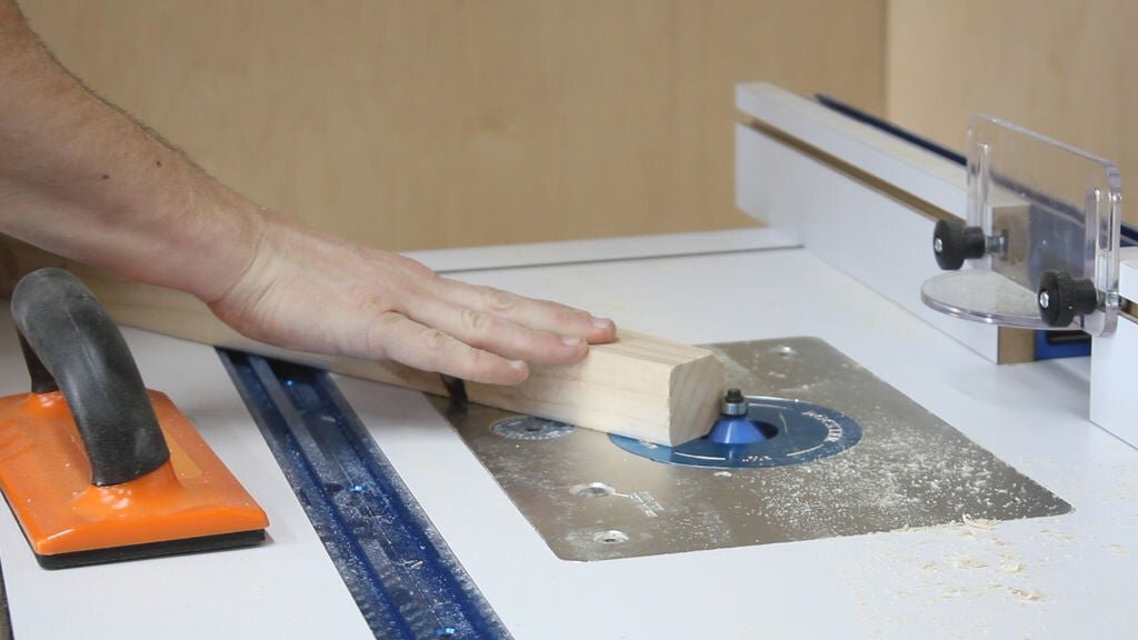
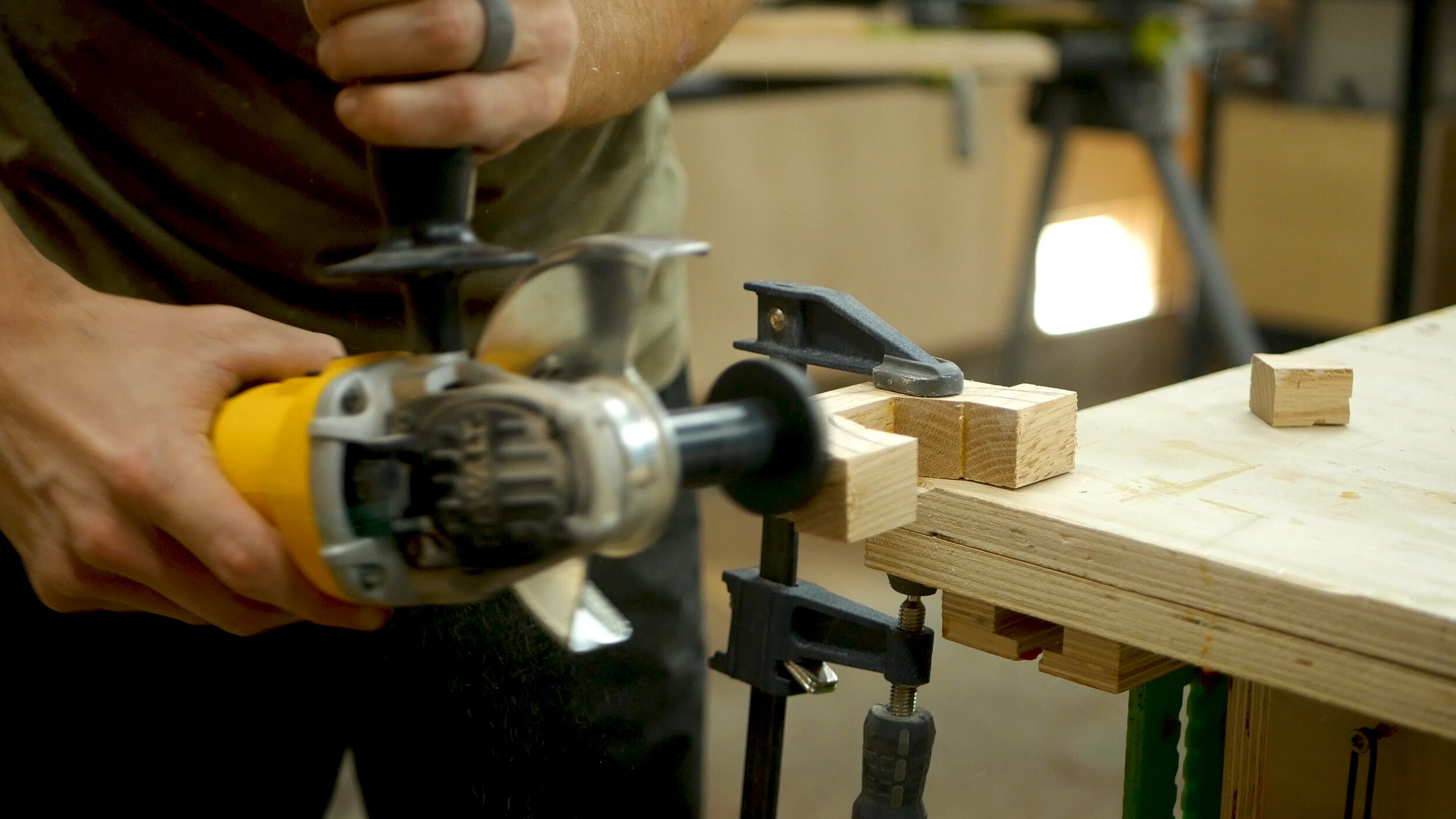
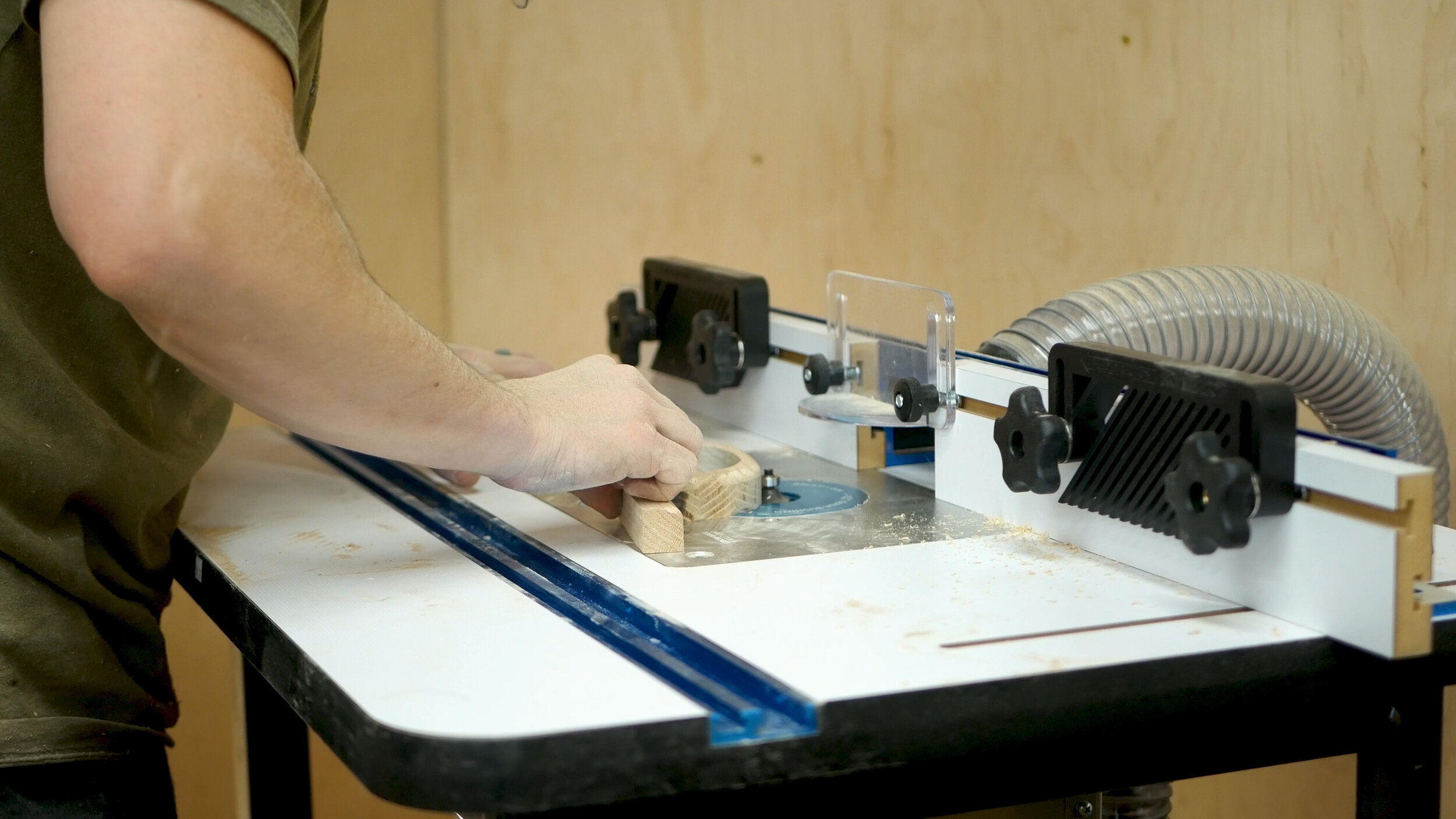
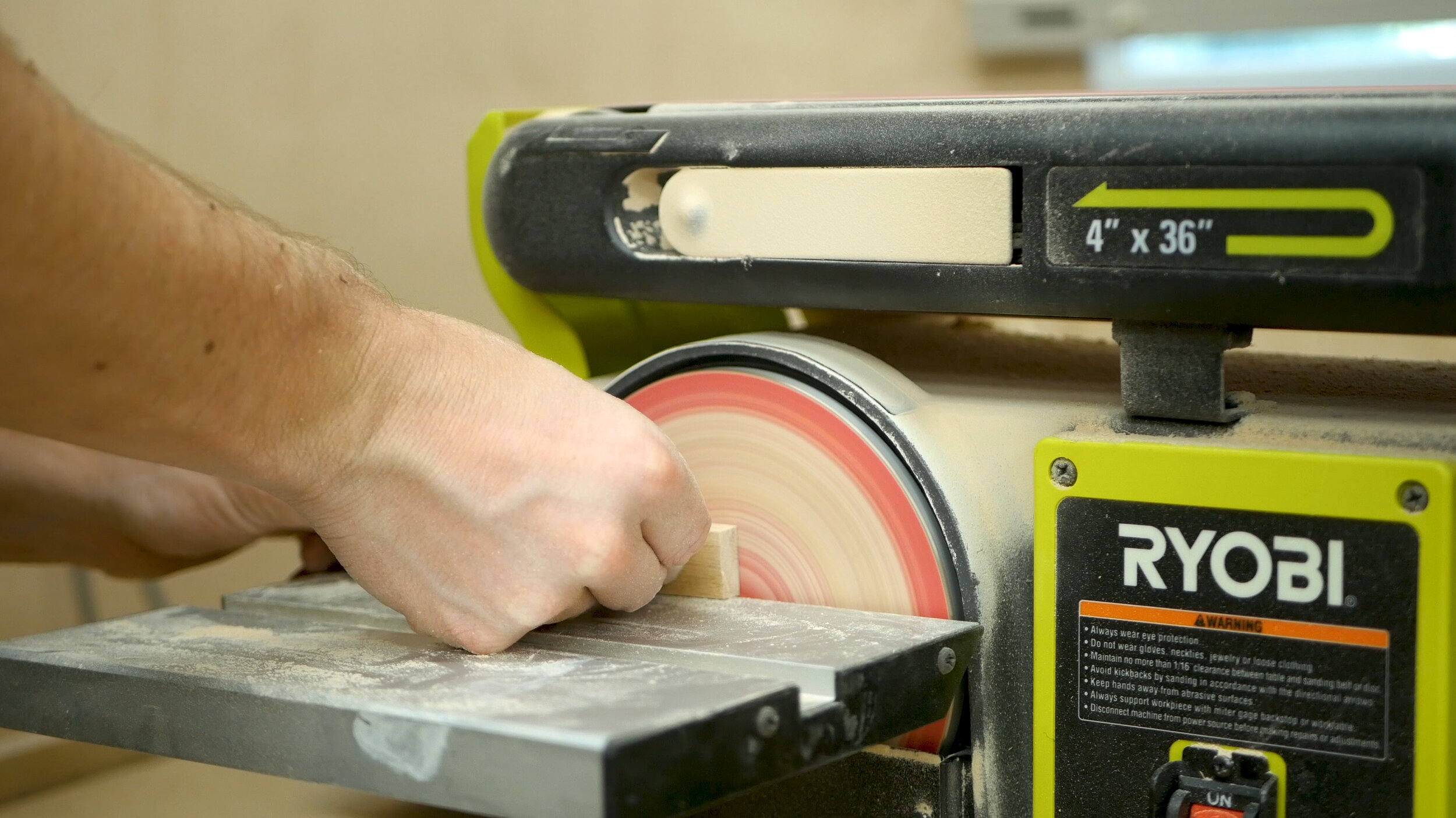
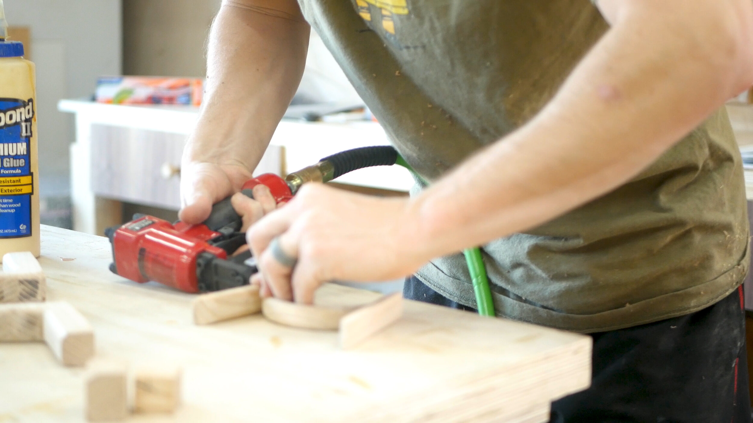
Once it was dry the next day, I could use the mini turbo from Arbortech to grind down and shape it into a rounded form. Once smooth, I rounded over the corners at the router table. I then made a series of smaller curved and flat pieces, and tacked them all together with glue and pin nails - forming the final stirrup (last picture).

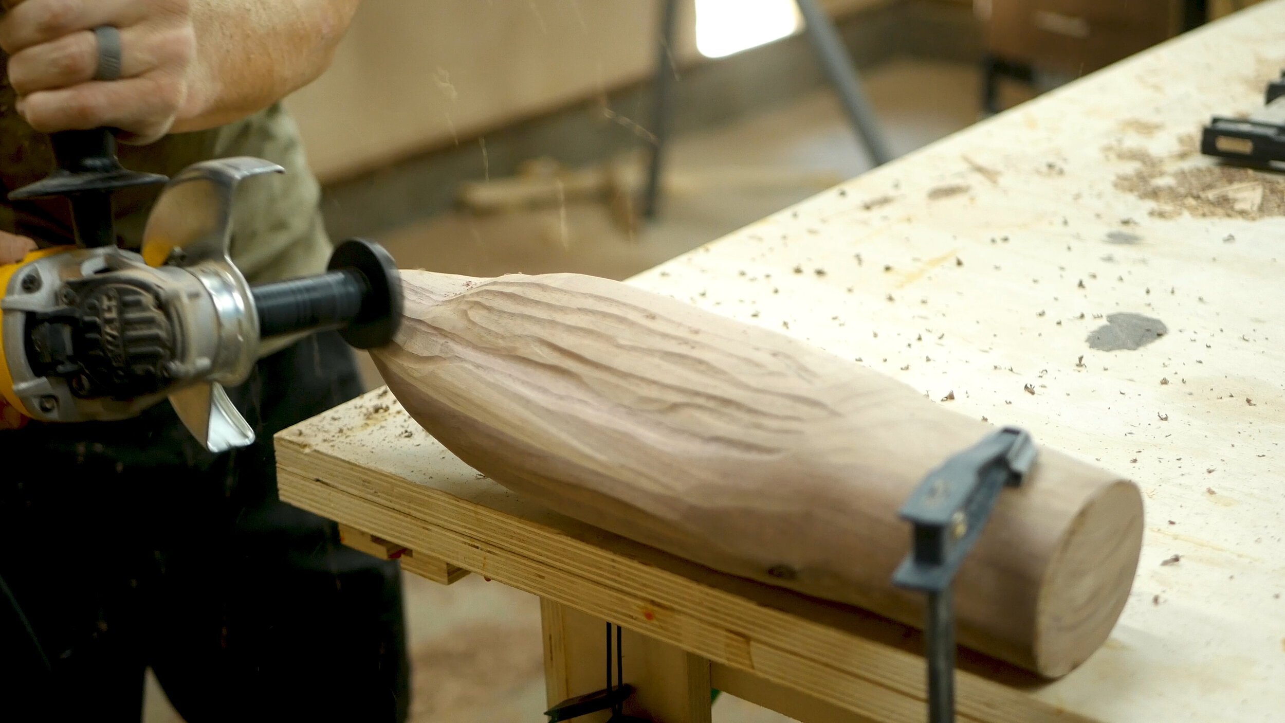
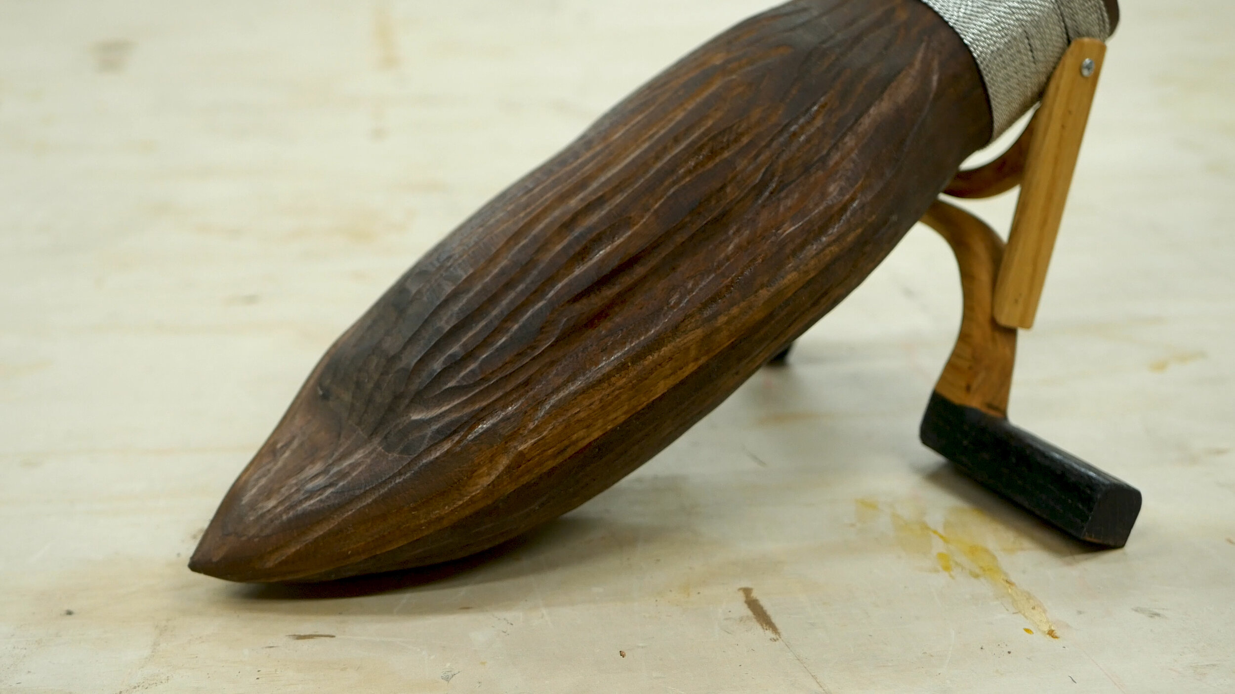
While the stirrup pieces cured, I could turn my attention back to the broom portion of the build. The goal was pretty simple - power carve down the stacked walnut into a broom shape. I looked at quite a few reference photos throughout the process. The Turboplane created the shape I needed (Pic 1), followed by a flap disk to smooth things over (Pic 2).

I then used my bench top sander (Pic 3) to round over the base of the bristles, and then the mini grinder to add some texture to the actual broom (Pic 4).

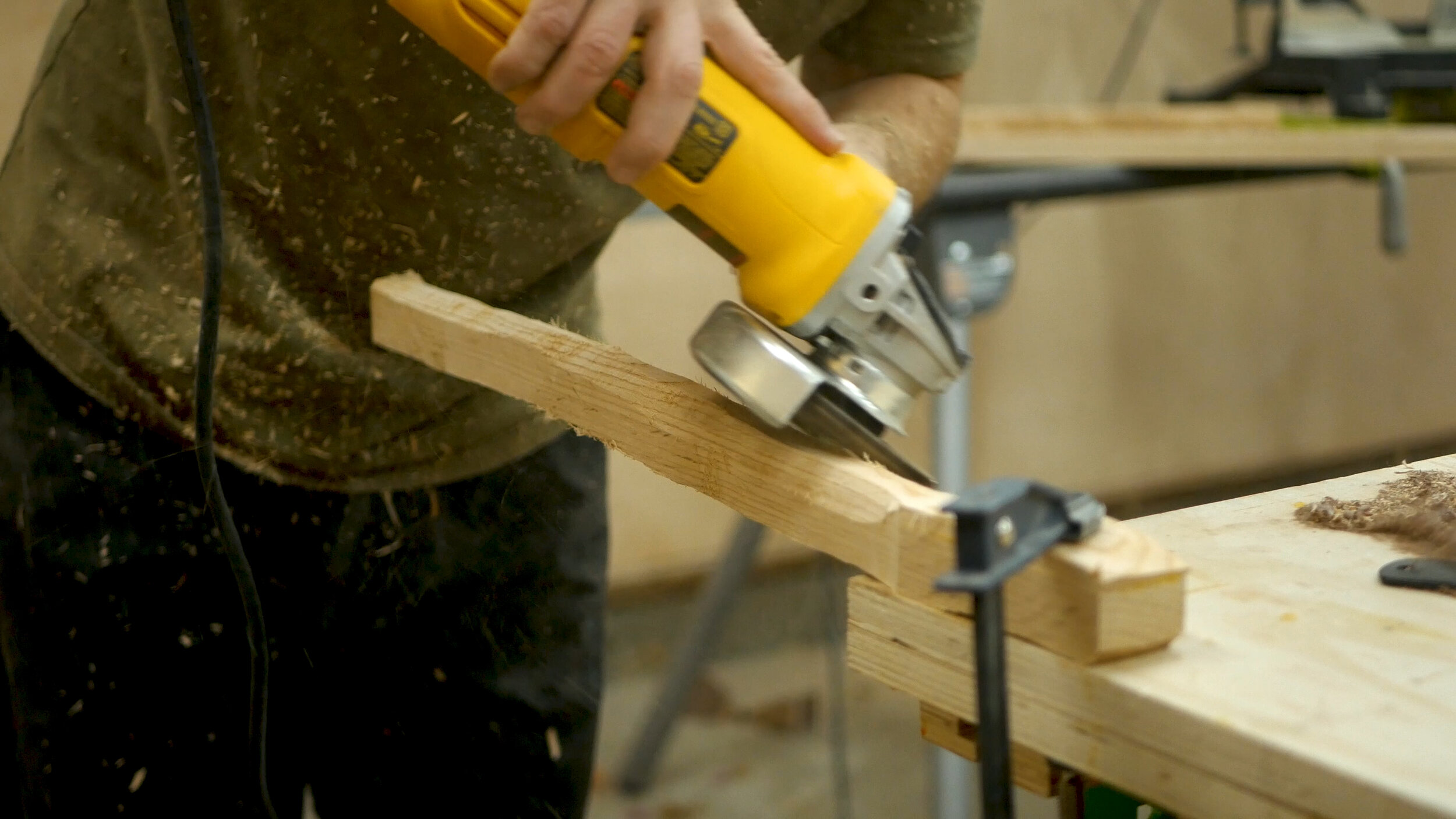
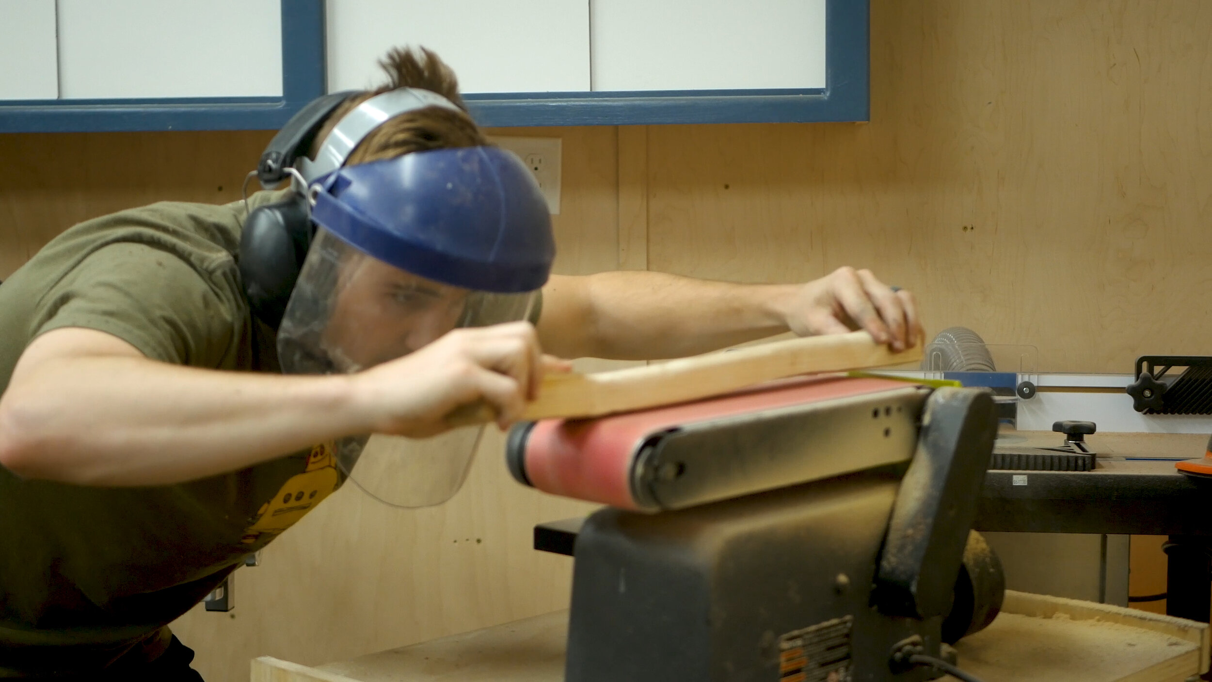
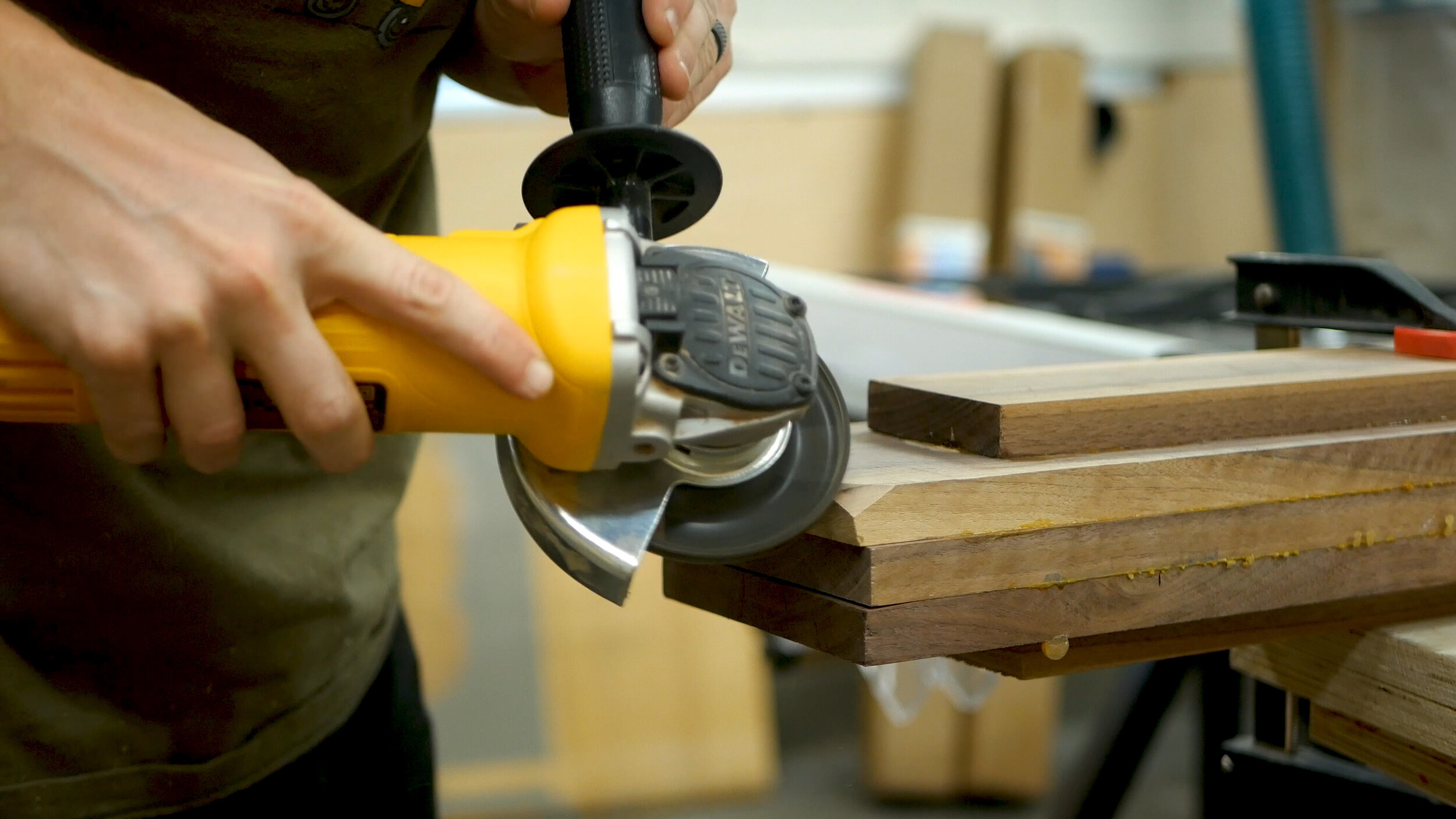
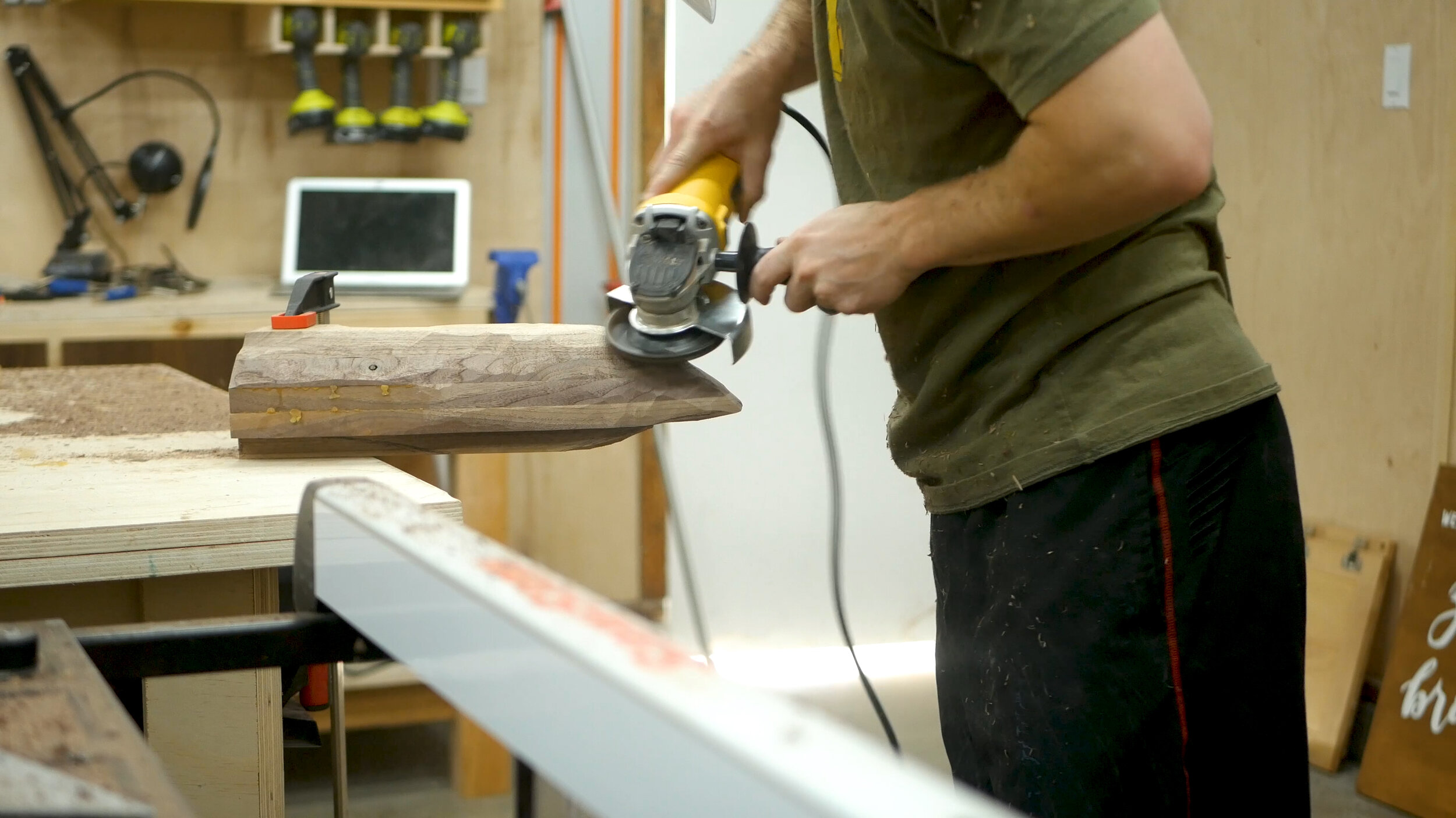
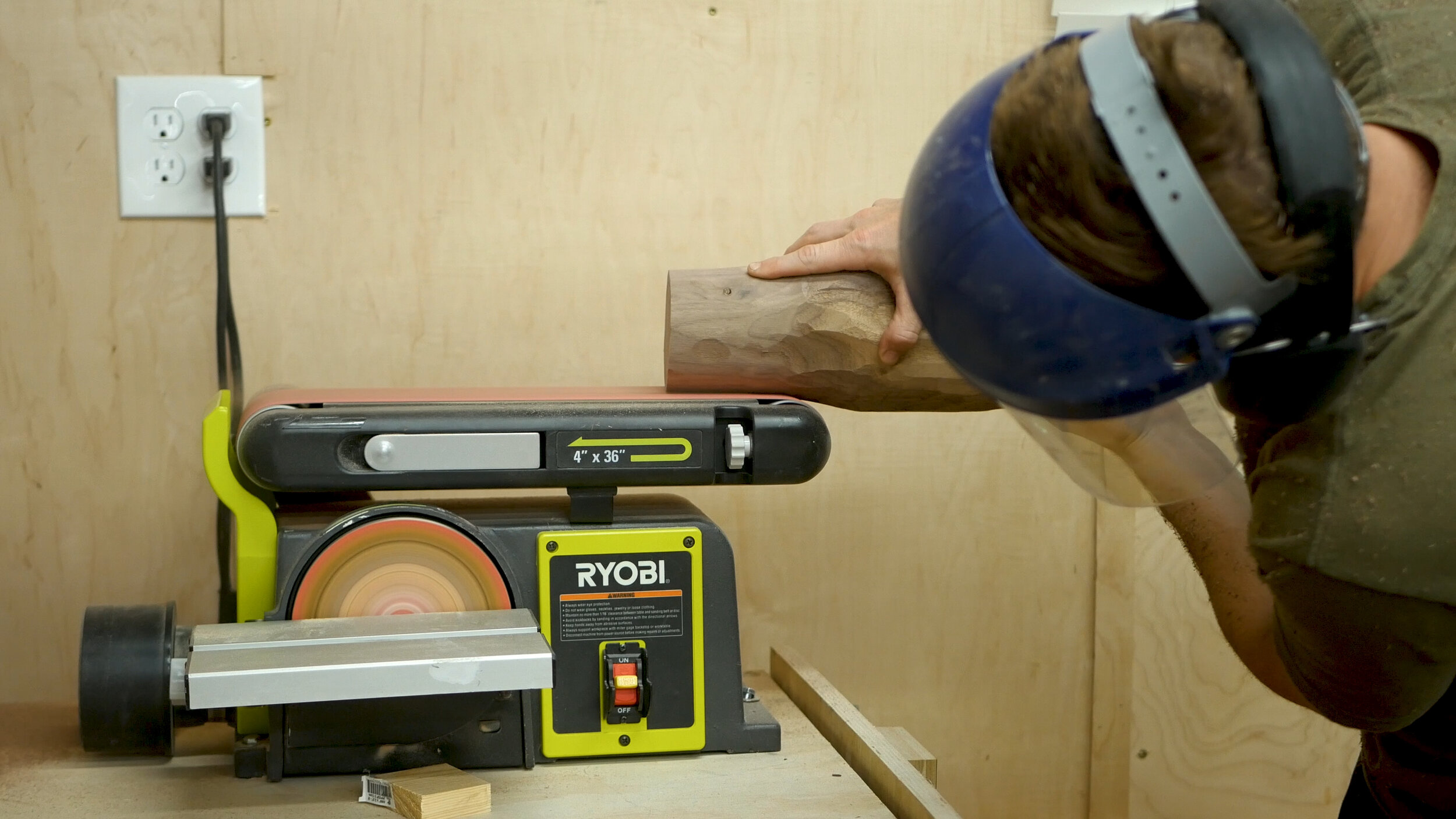
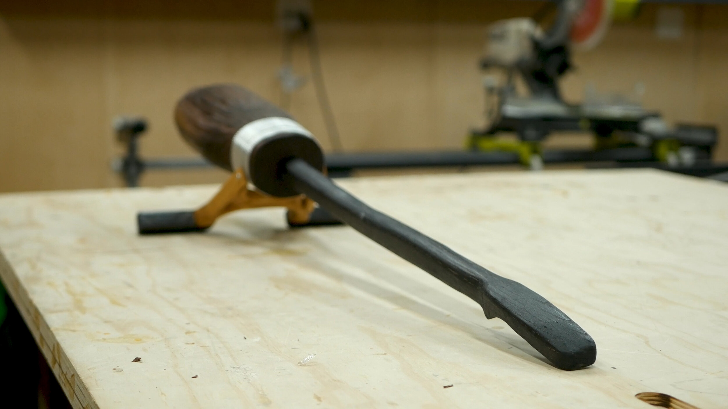
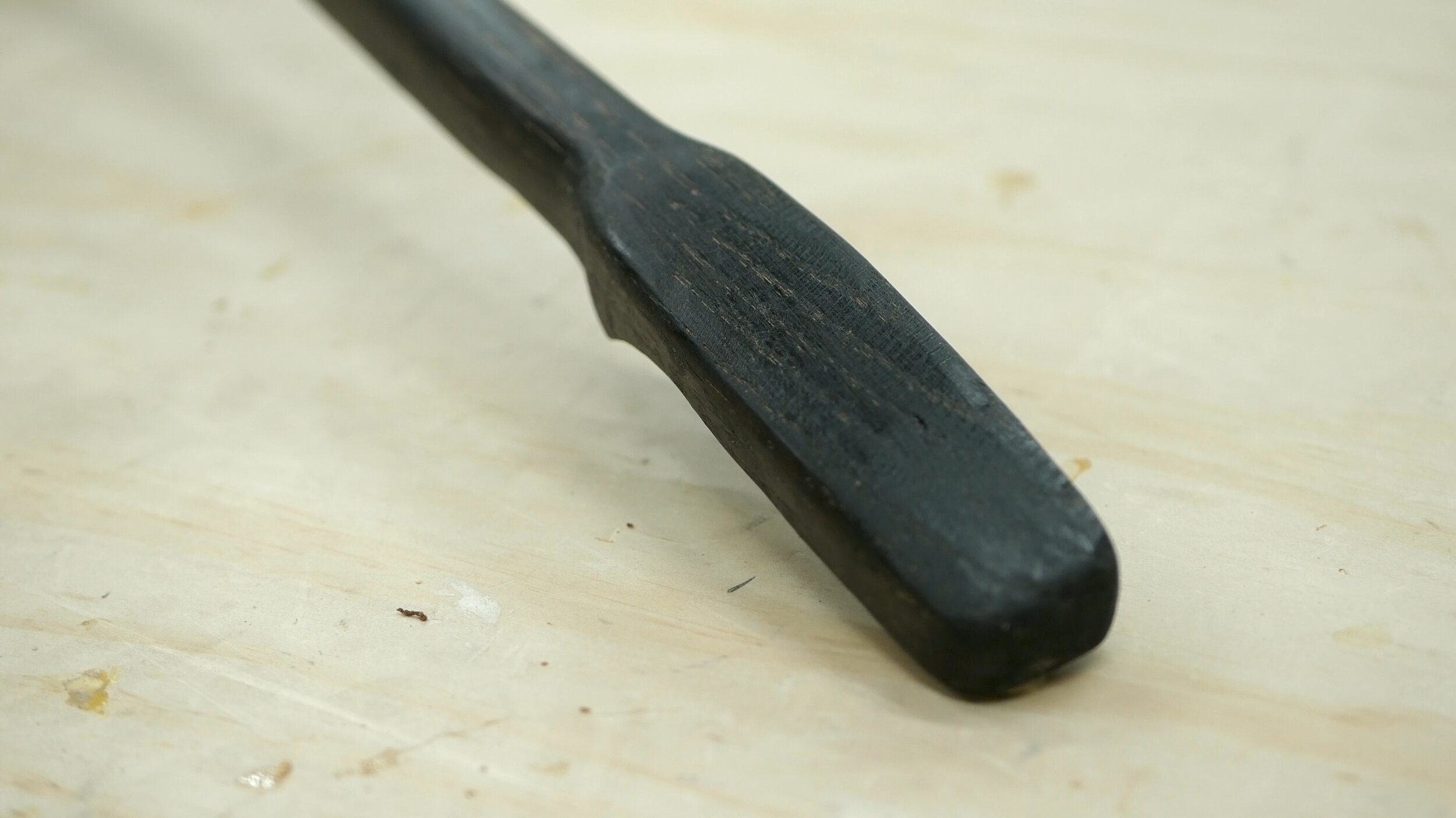
The next step was relatively the same as before. I used the Turboplane a flap disc on my angle grinder to shape the handle (Pic 1). This again was done using reference photos and eyeballing the broom handle tip. I then used my benchtop sander again (Pic 2) to help flatten and smooth out the overall shape.

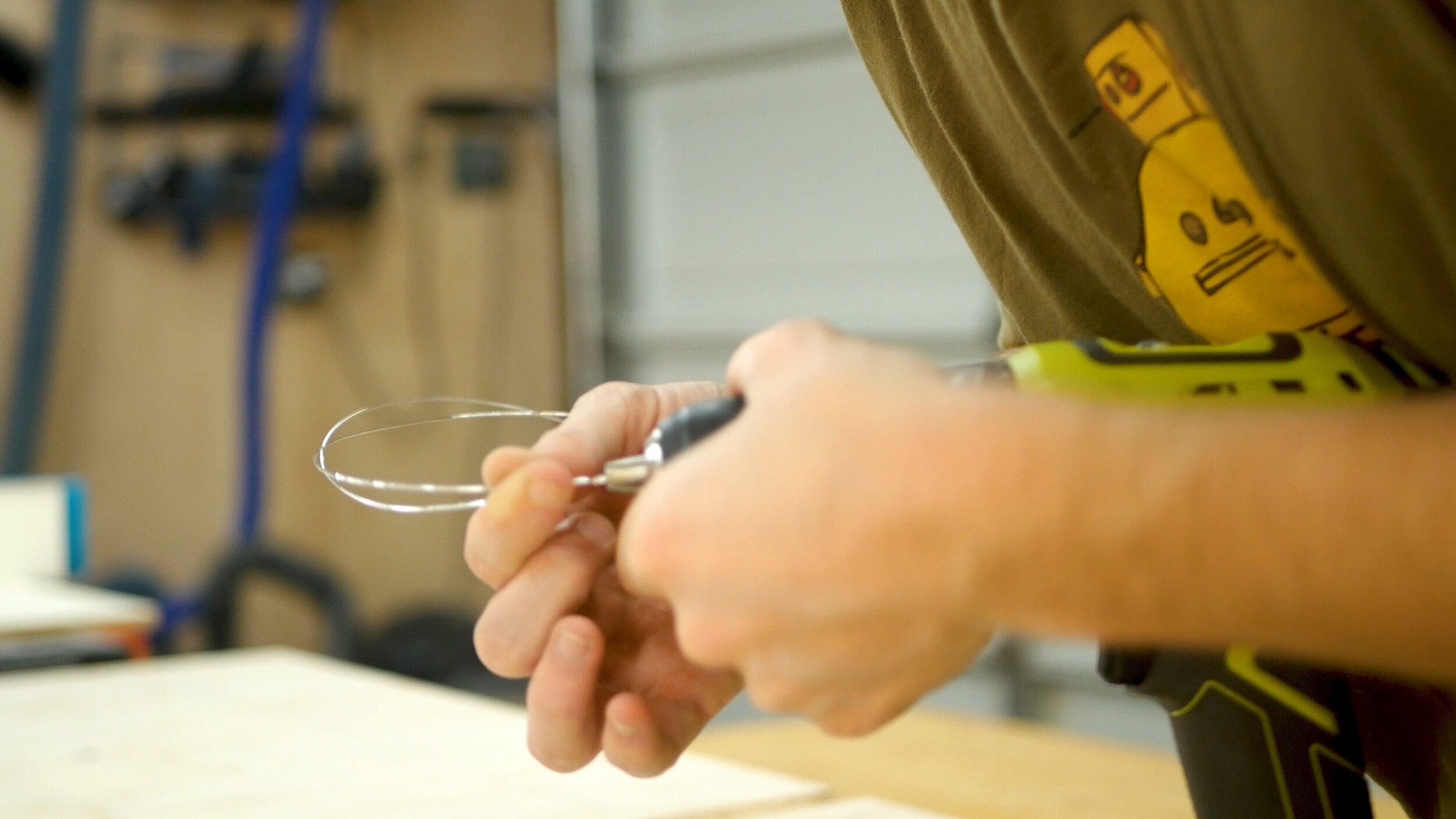
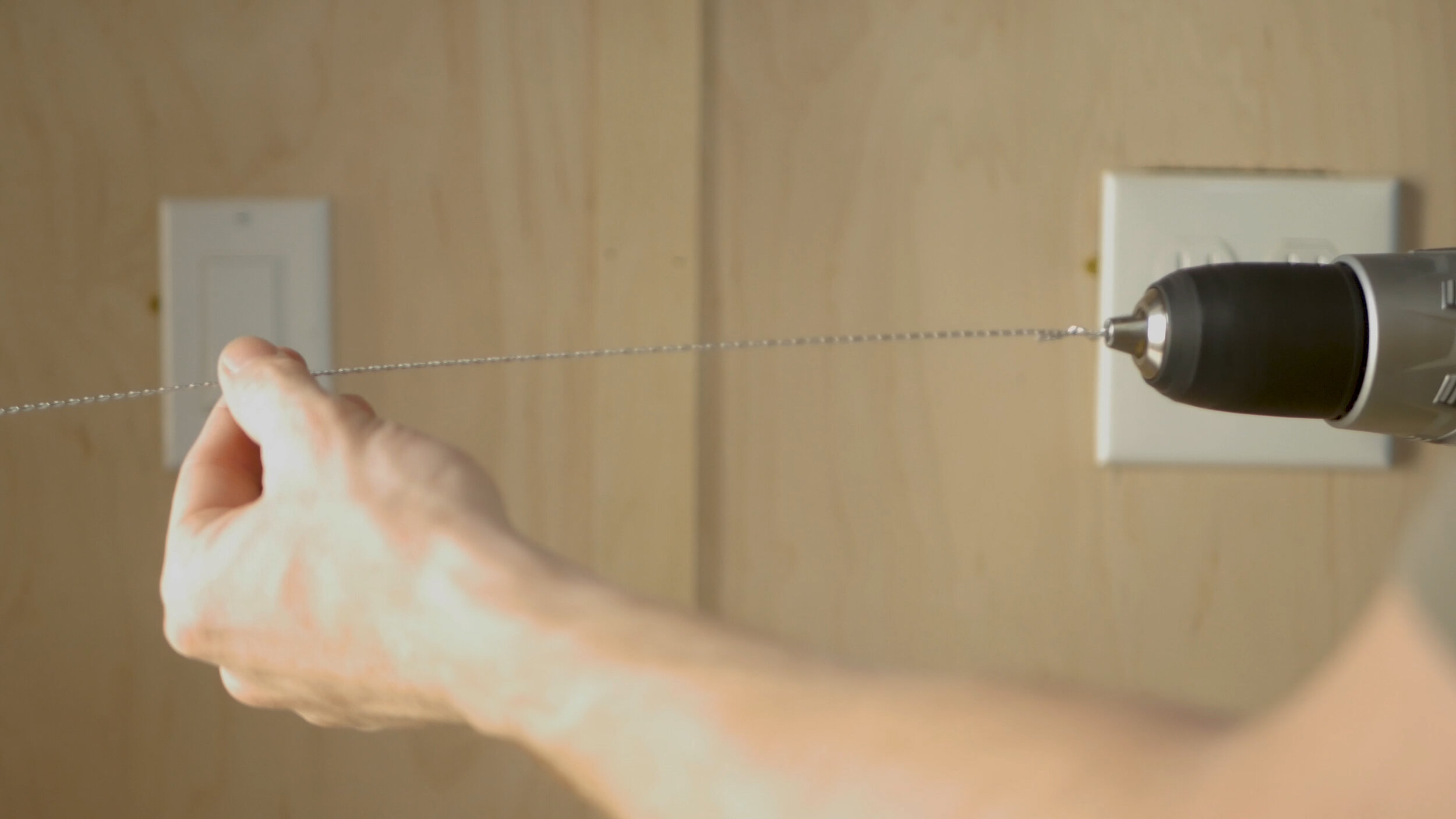
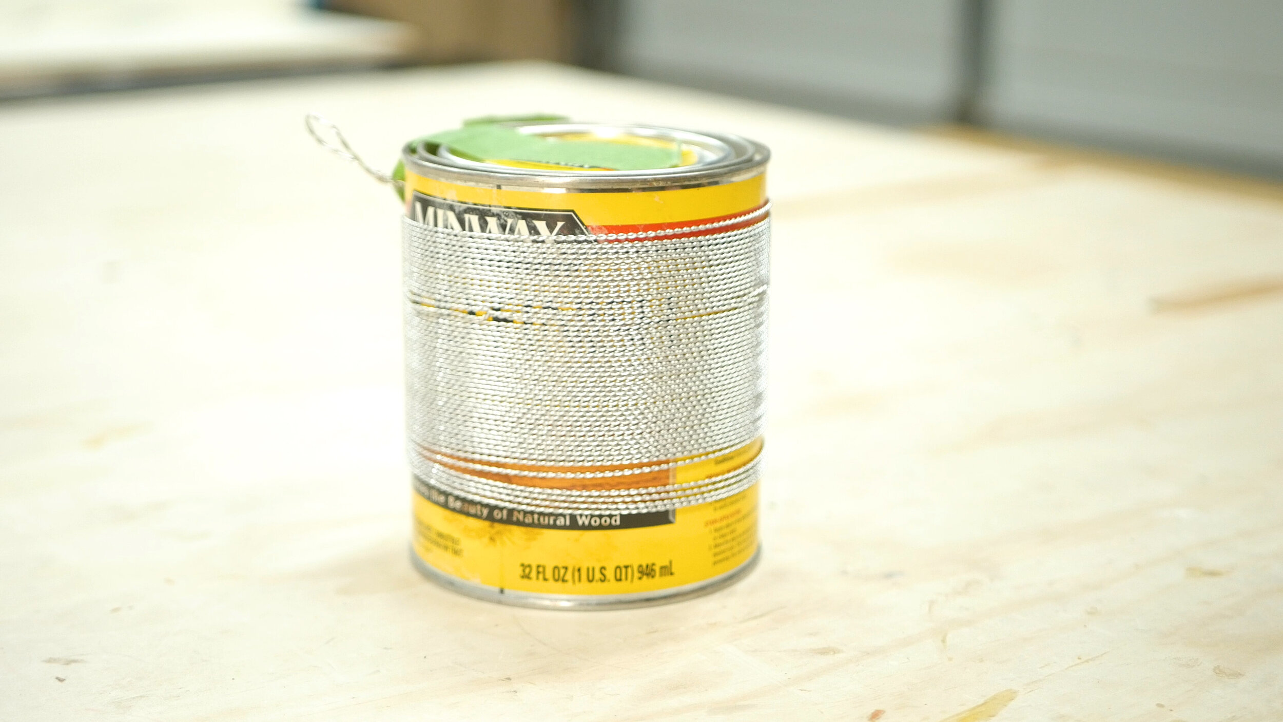
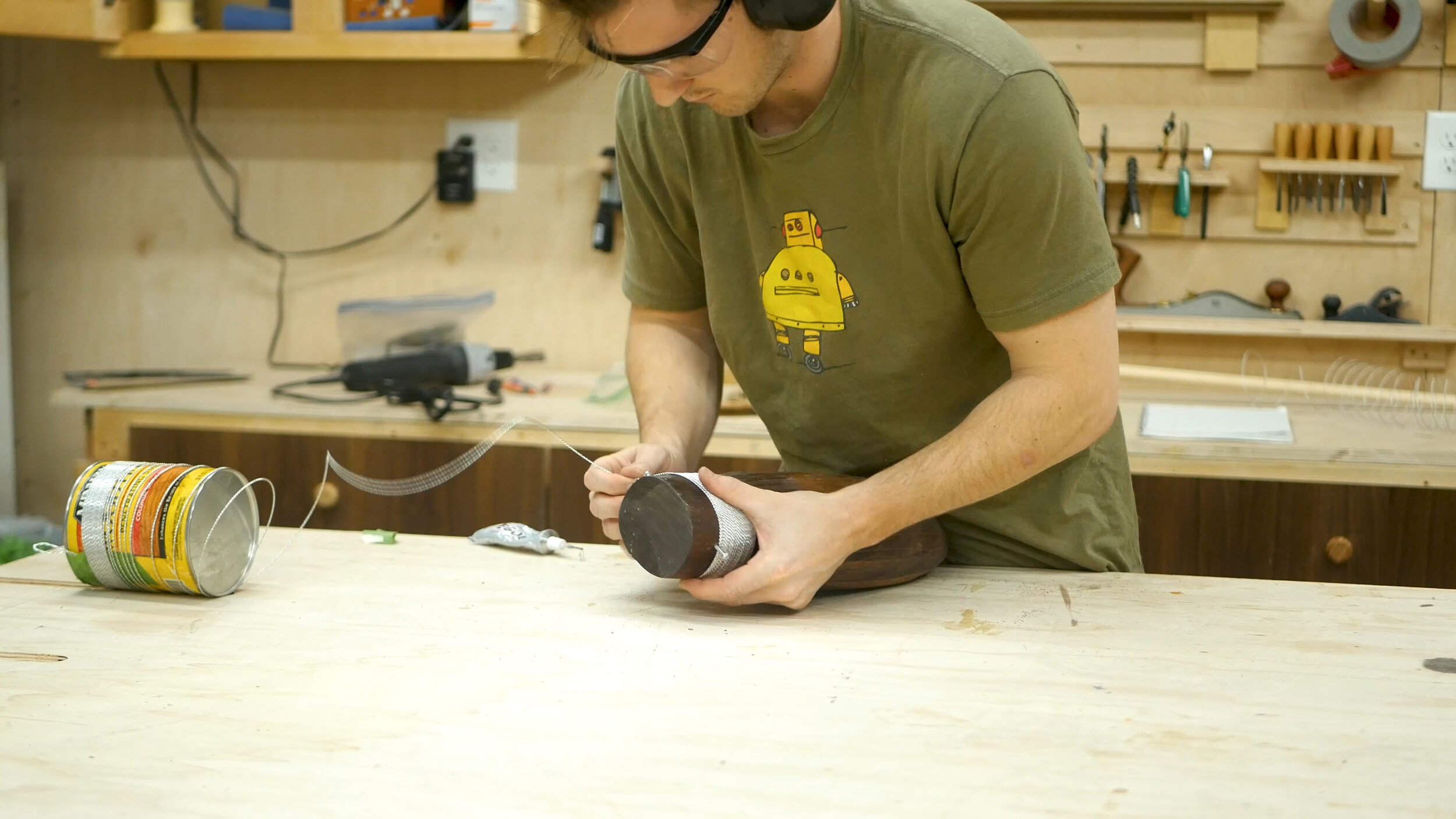
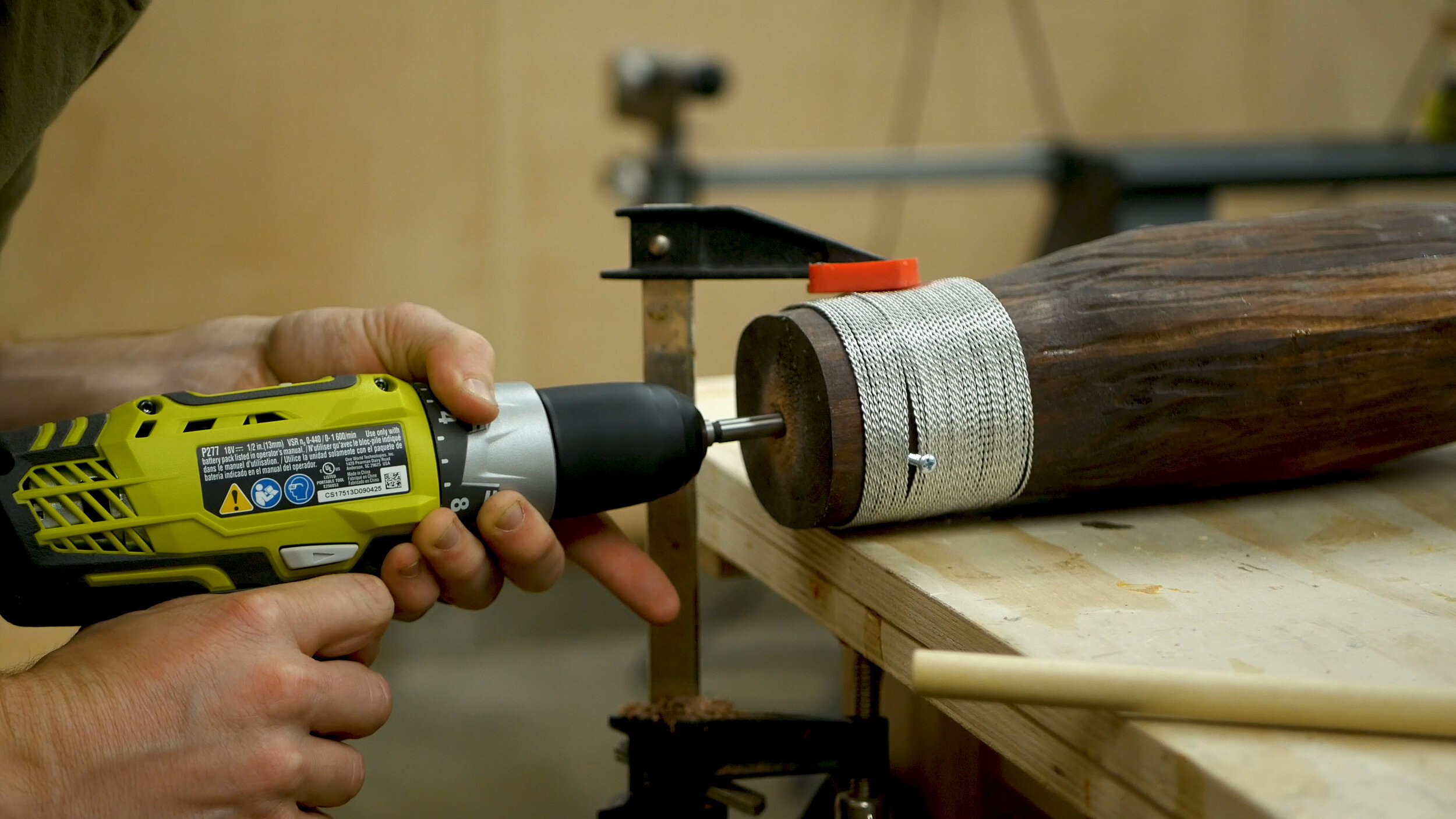
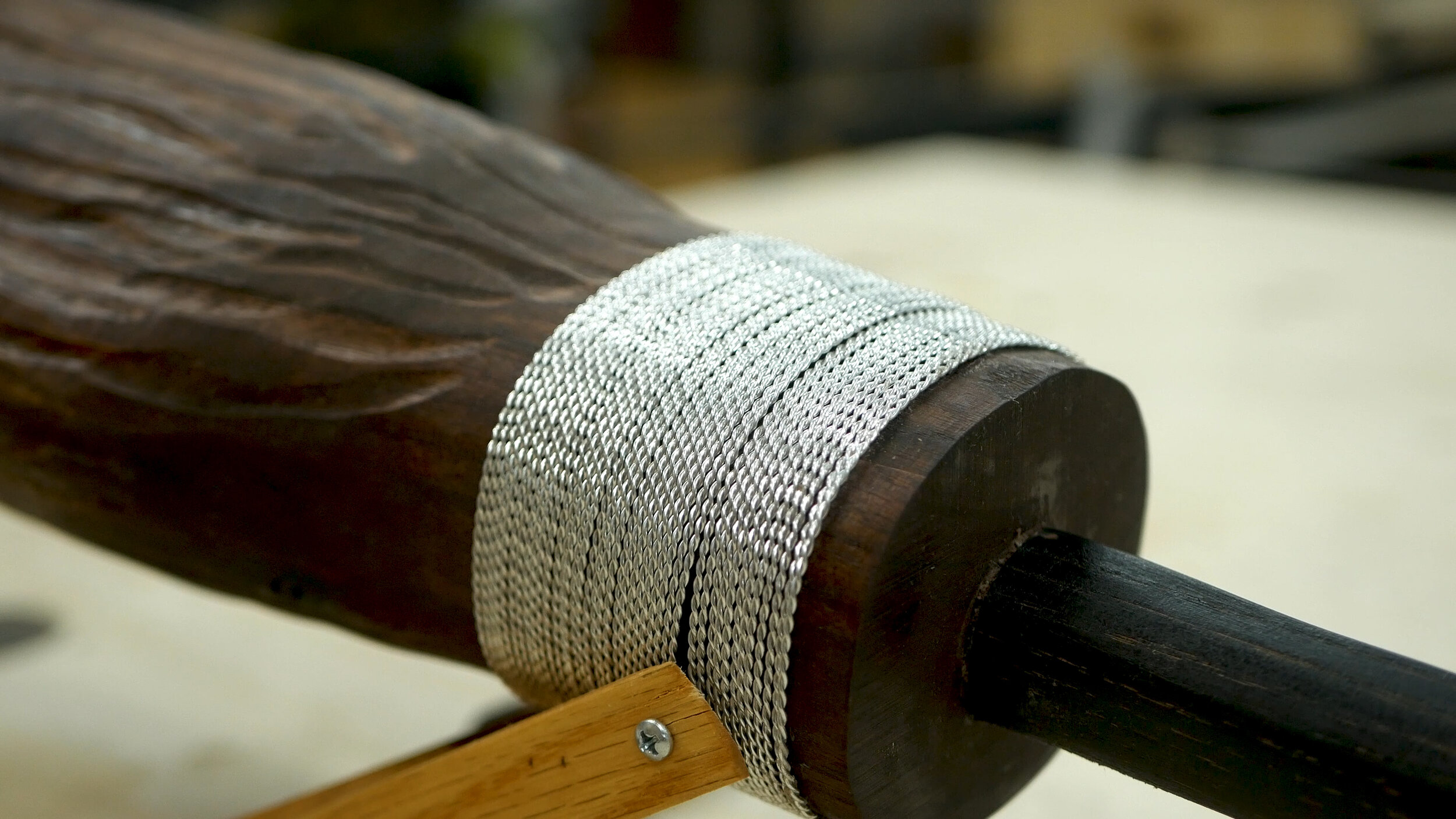
The Nimbus 2001 has a silver type material around the broom portion - I’m guessing in a practical world, the role of it is to clasp the bristles against the handle. Obviously this is a magic broom and used for flying, so we can just get creative with DIY. I considered using very thin steal and wrapping it around, but I thought instead I could twist thing MIG welding wire together to create something that wrapped around the broom. By chucking it up in the drill and just twisting, it worked quite well. I then wrapped it around a paint can. Ideally, you’d heat the wire after this to get rid of twist and tension, but I don’t have those tools. It was fine, it just meant I had to be careful when transferring it to the project.

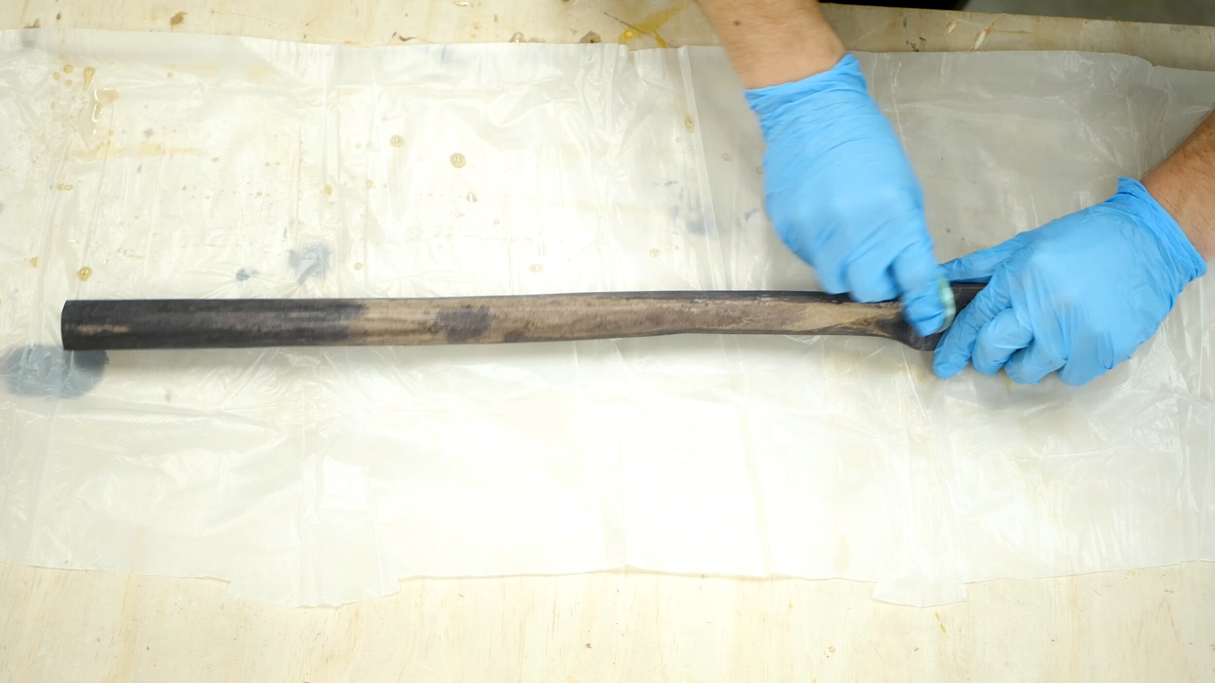
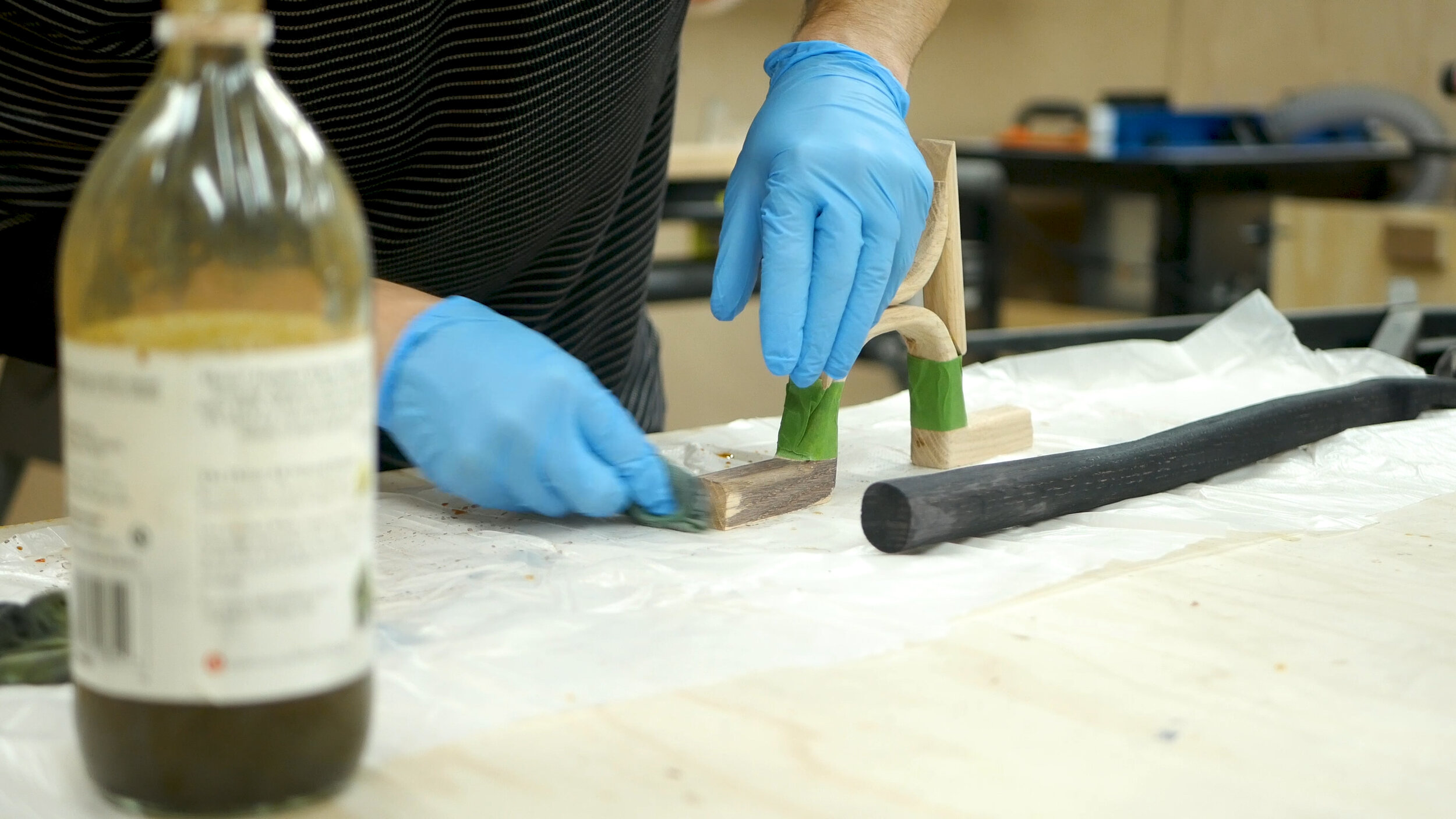
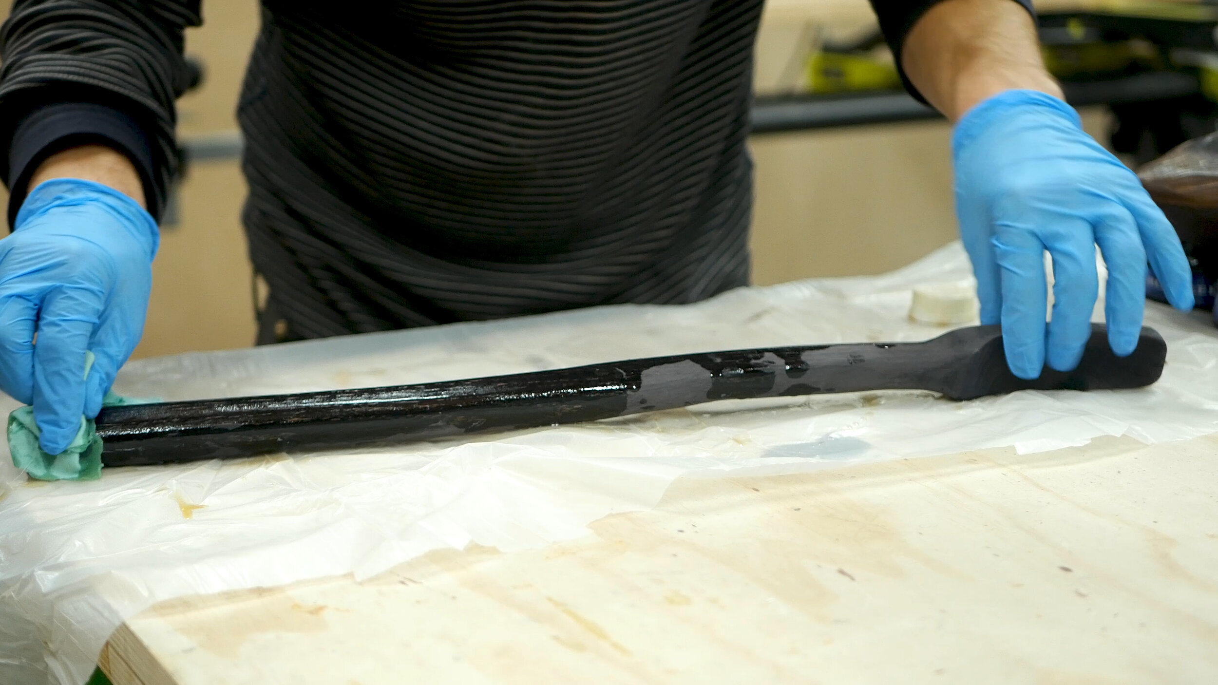
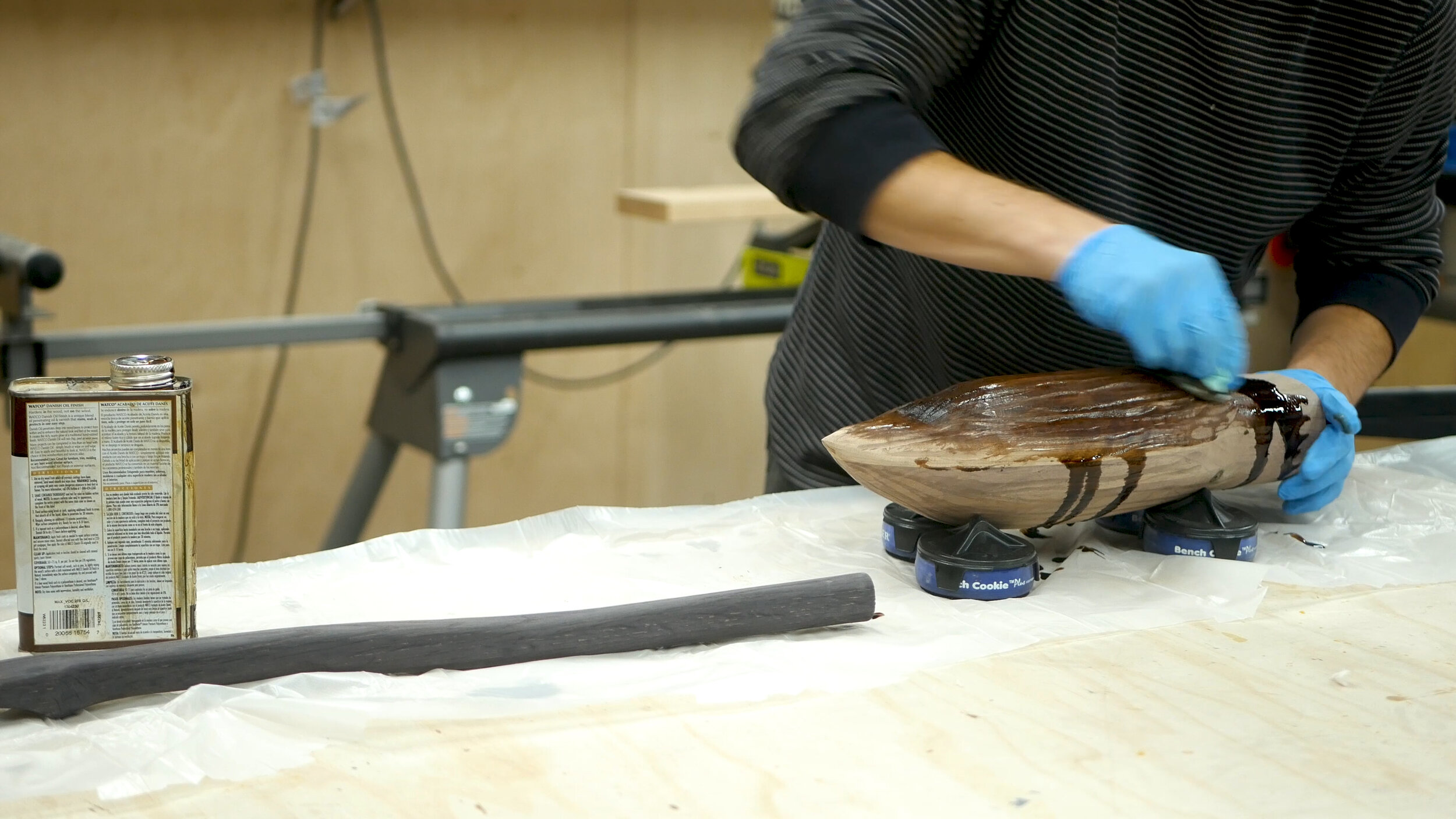
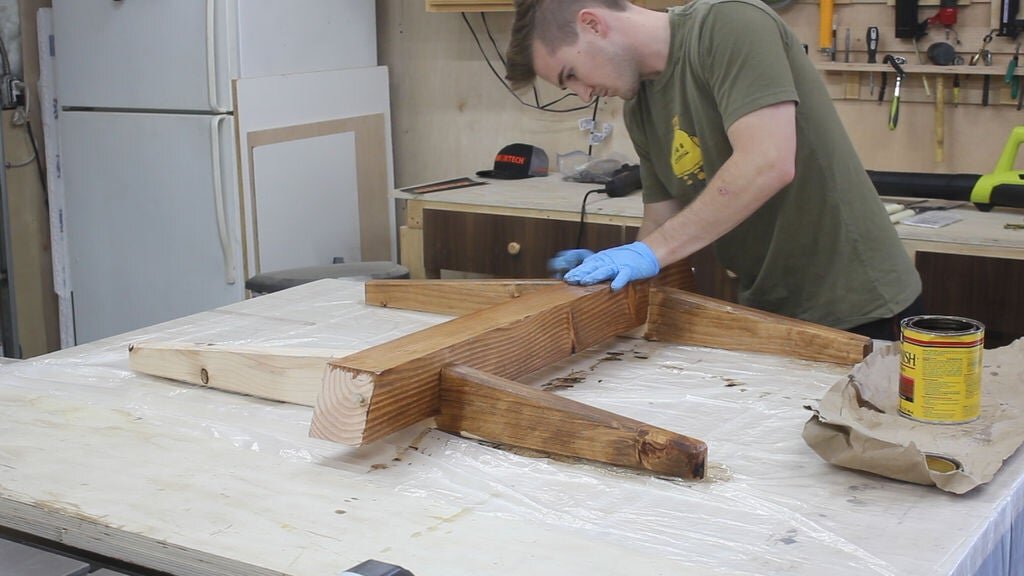
The Nimbus 2001 is black and dark brown. To achieve this look, I used a vinegar+steel wool solution to oxidize the white oak - it’s incredible how black it turns almost instantly. I also did it for the foot portion of the stirrups. I then used a coat of clear danish oil to give it protection and shine, and some dark walnut danish oil to bring out the dark and rich contrast of the walnut.

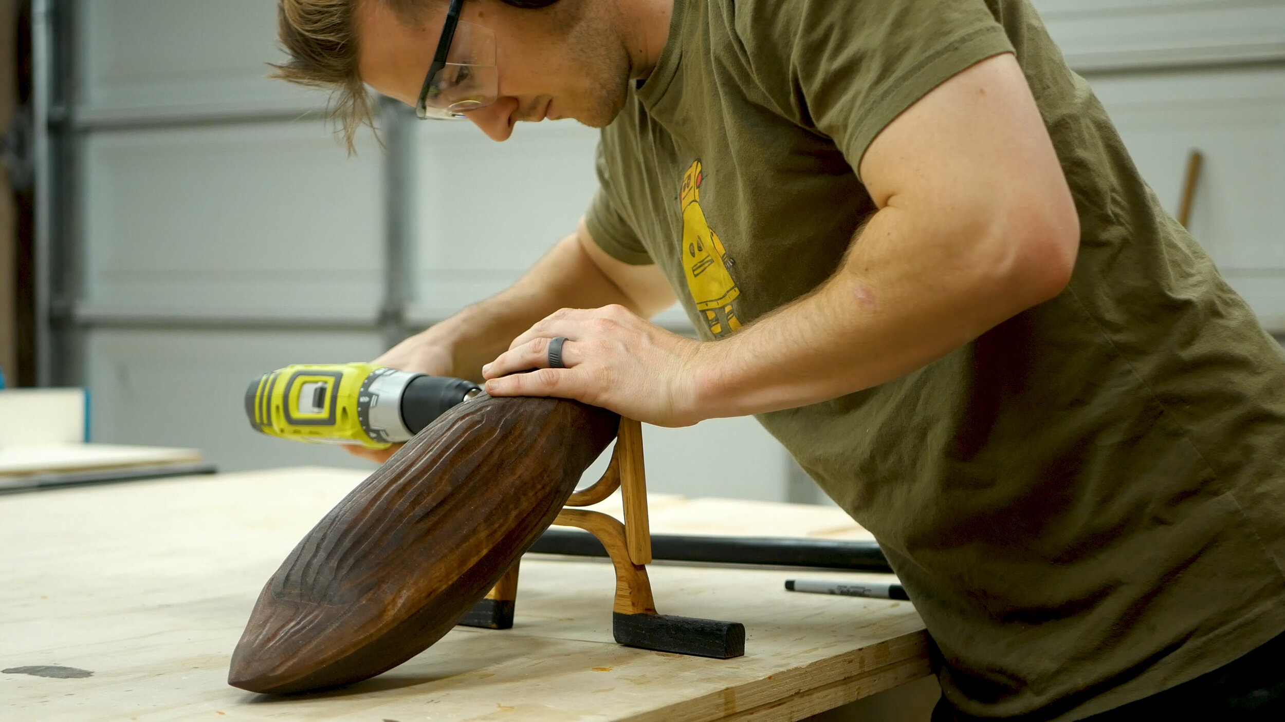
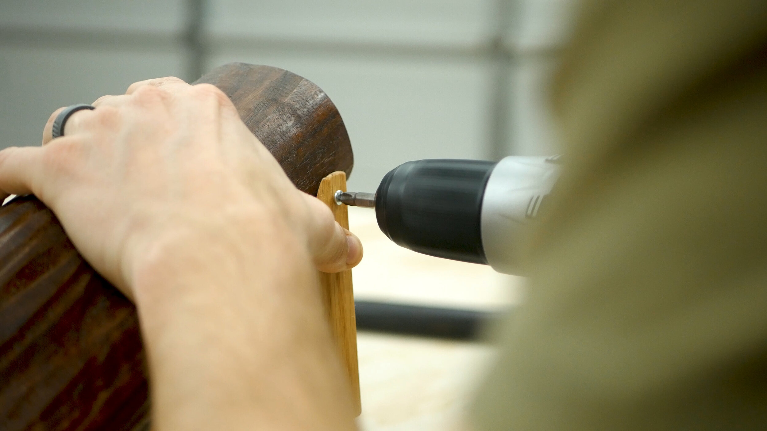
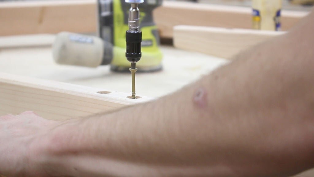
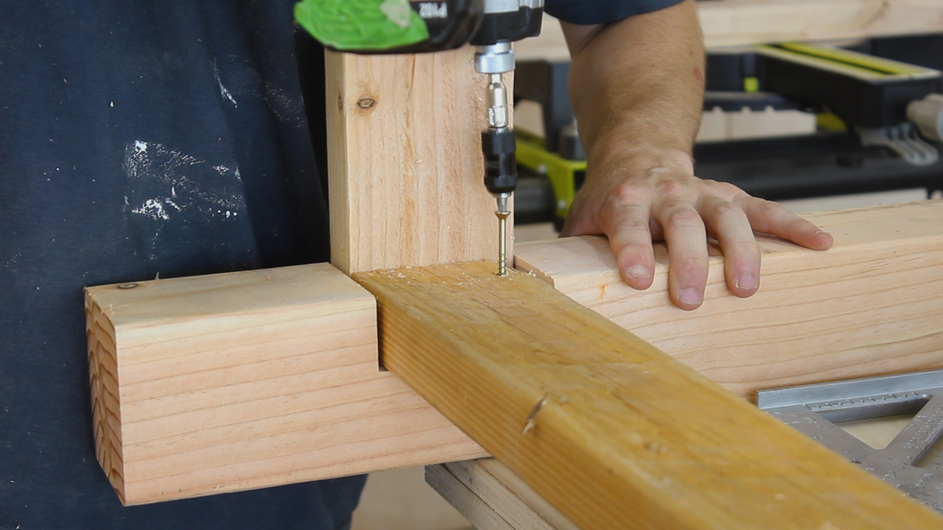
Last up was final finish prep steps before assembling. I drilled pilot holes for the stirrups and then attached using very small stainless steel screws. I then removed the stirrups, screw in the screws as reference, and slowly and carefully wrapped the broom with the twisted MIG wire. To secure it to the broom, I drilled little pilot holes, bent the wire into the holes, and I believe I epoxied them in. Very solid.

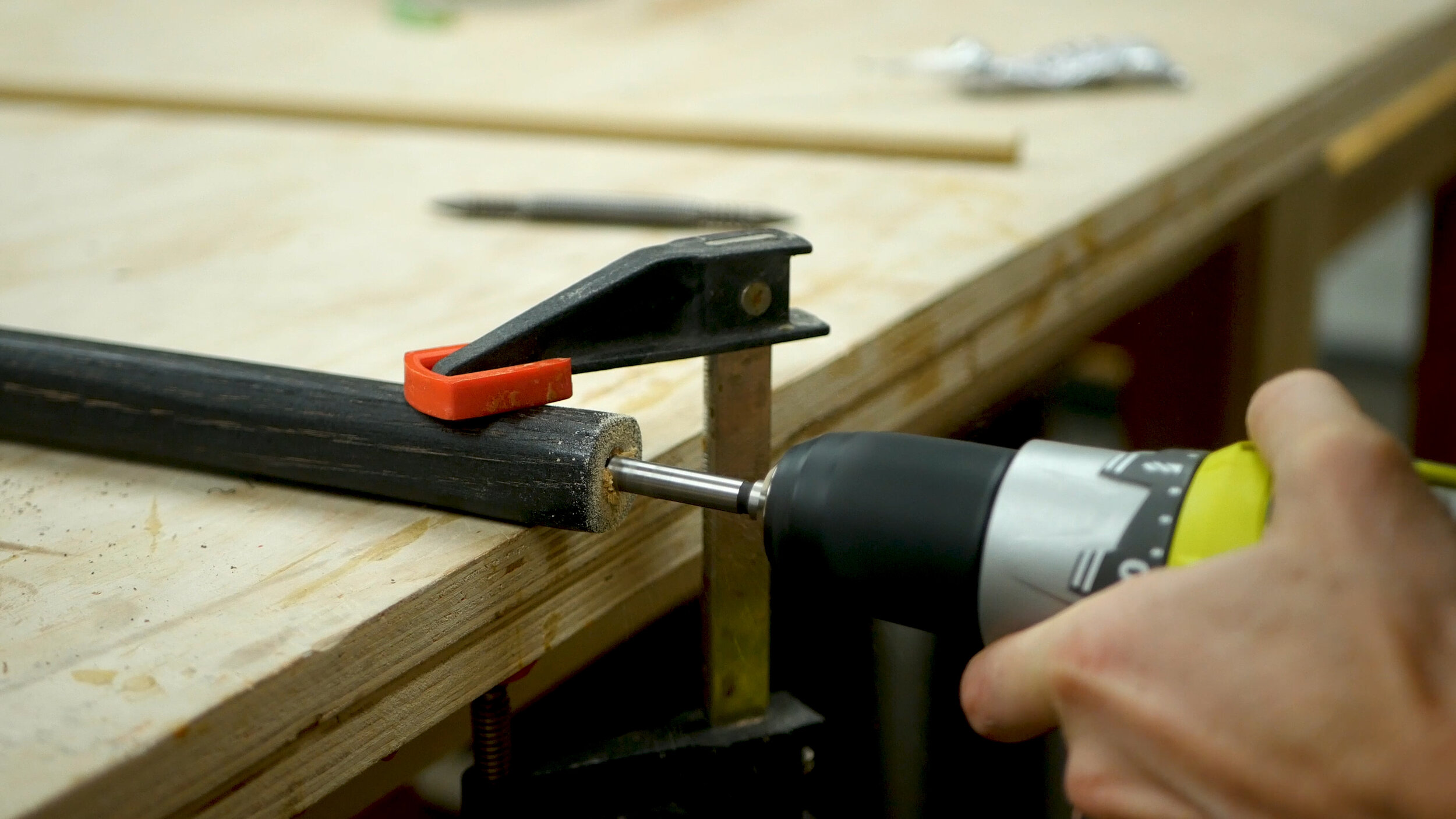
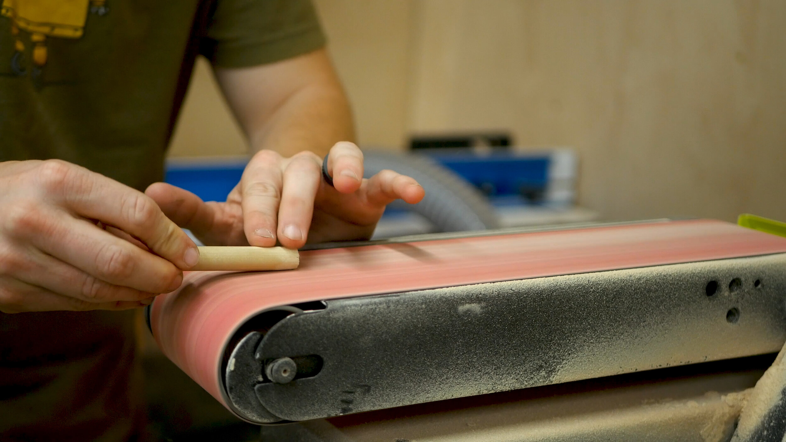
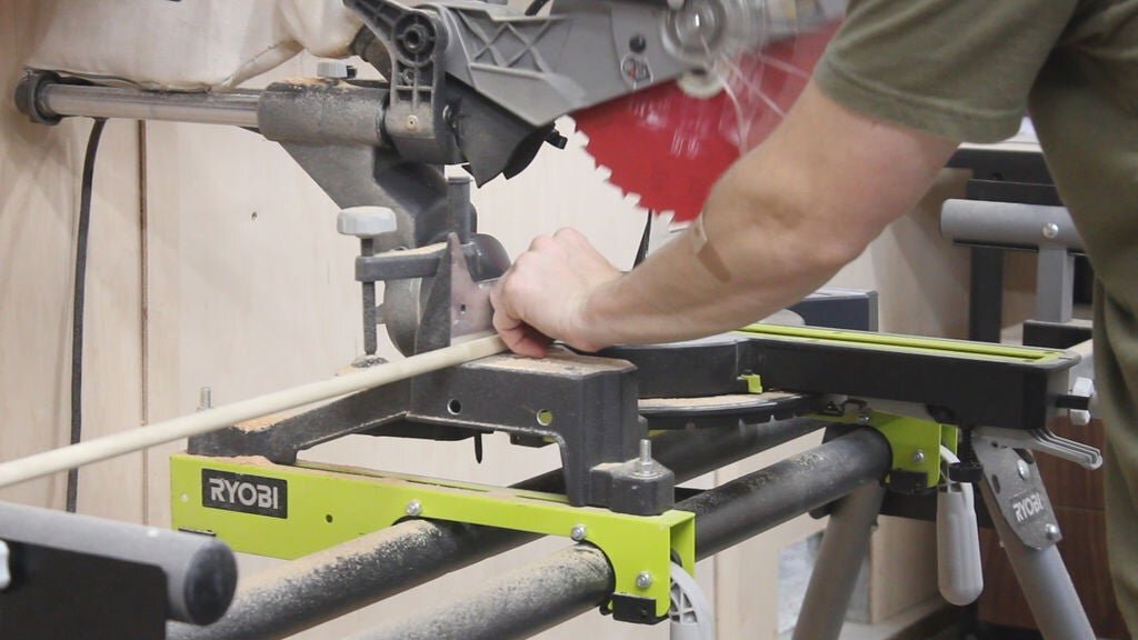
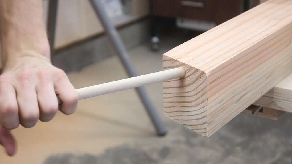
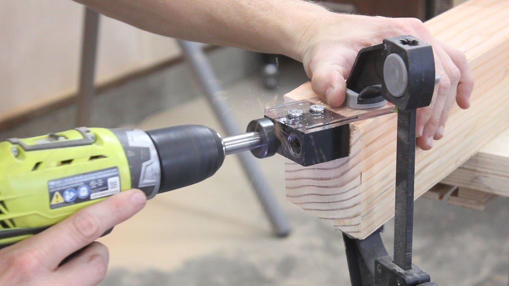
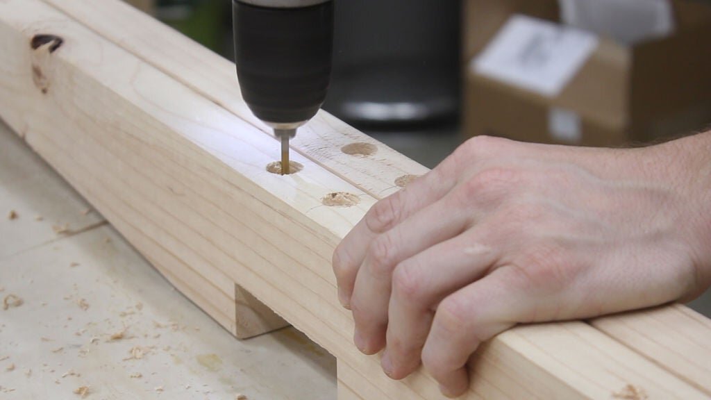
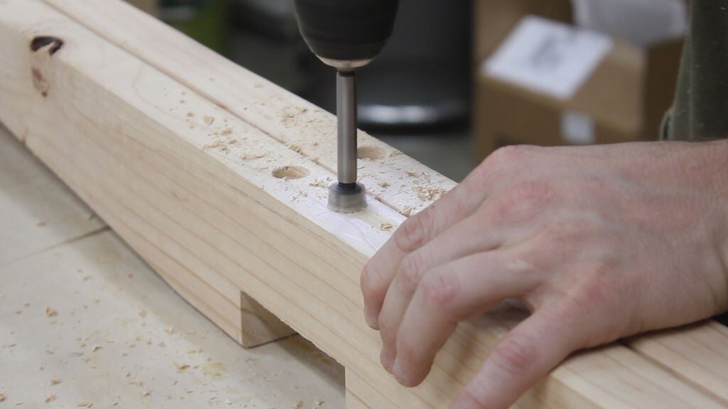
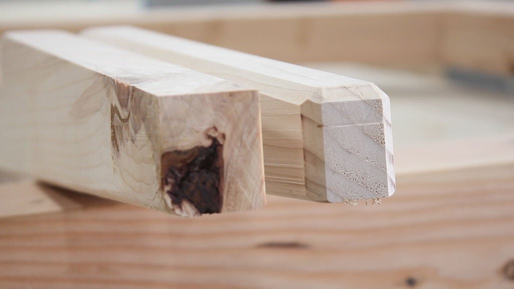
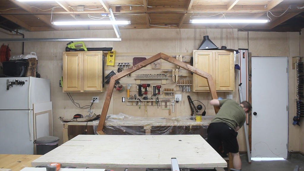
To connect it all together, I drilled a half inch pilot hole in each piece using a forstner bit (Pics 1-2). I then cut up and sanded down a dowel that I could insert into both ends with some glue Pic 3 , and then slowly clamped it all together Pic 4 using a single bar clamp. I took the clamping very slowly to ensure it was all lined up.

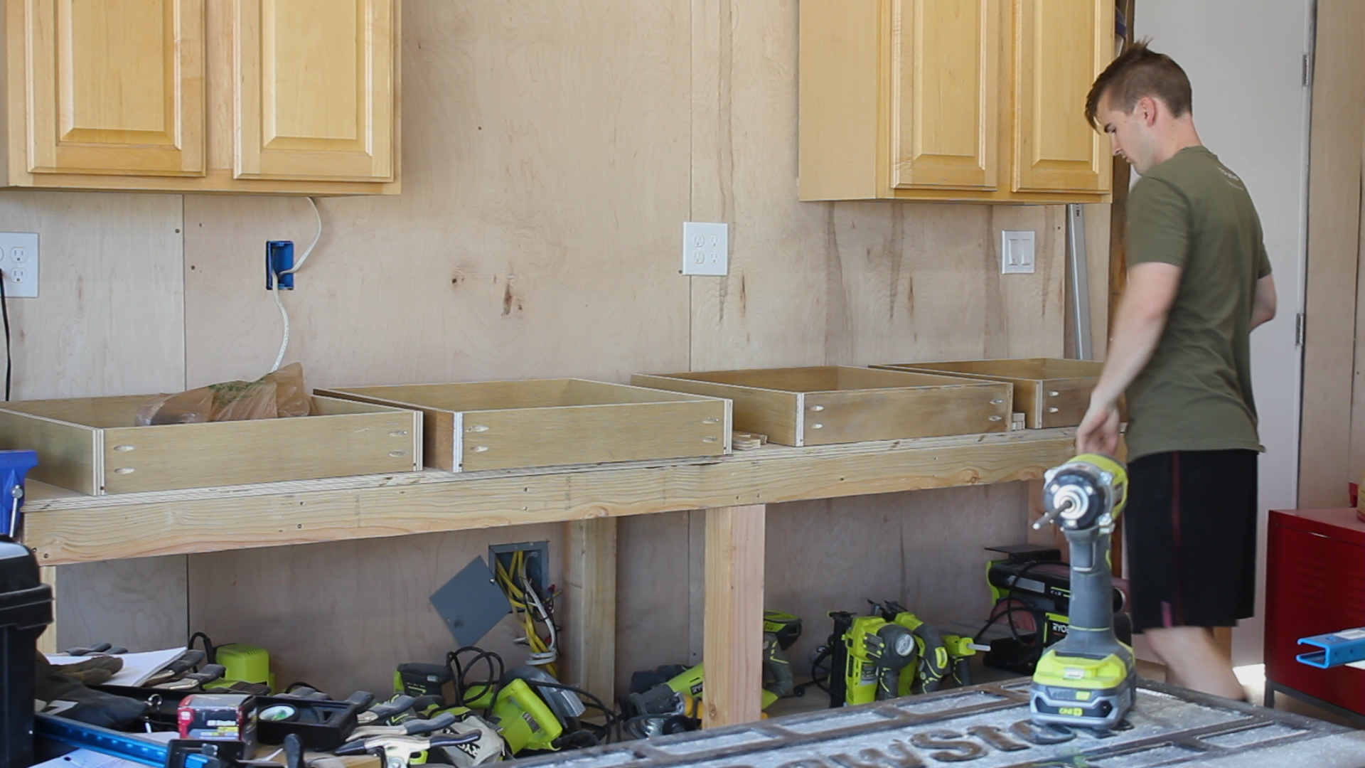
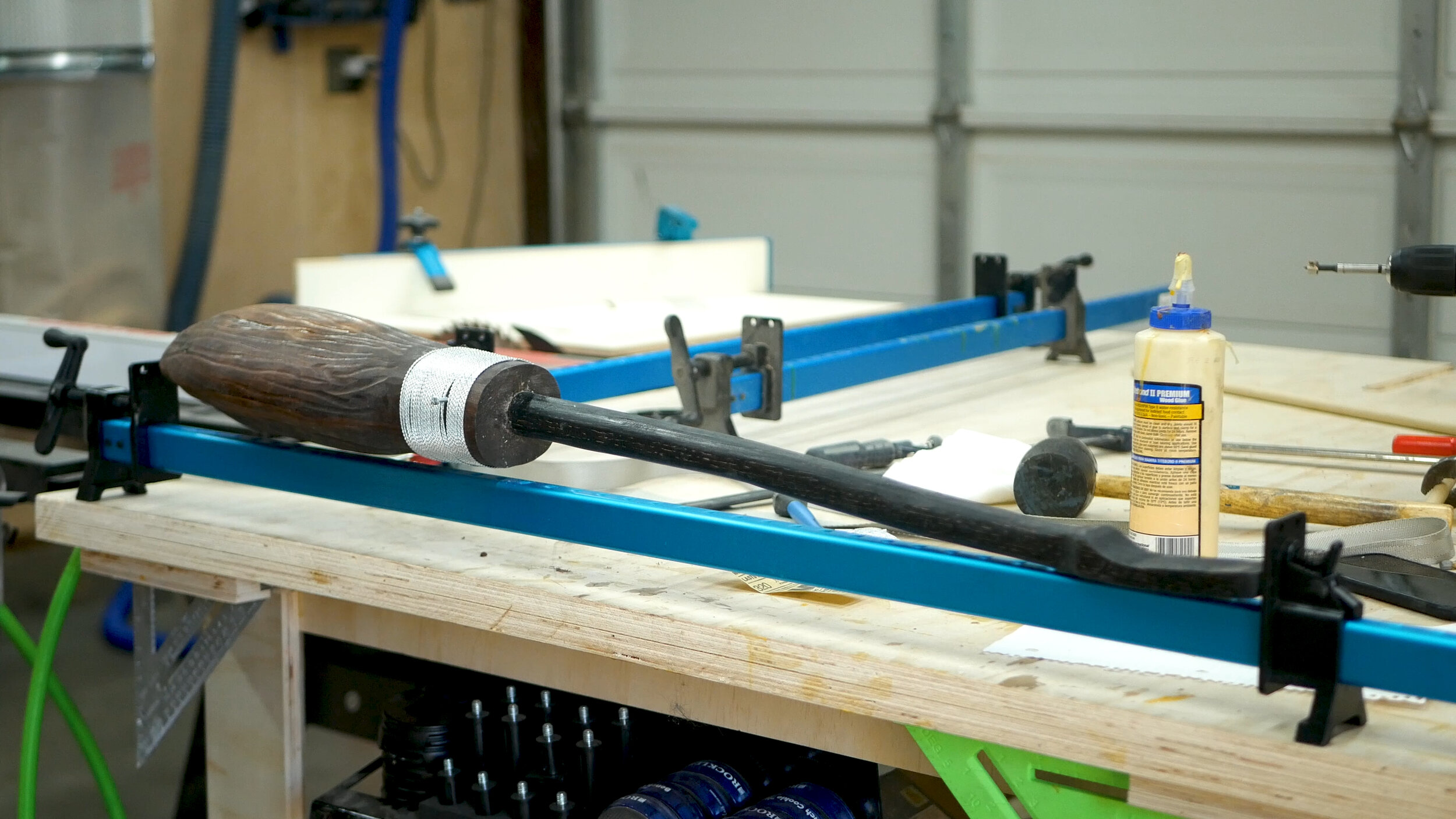
After screwing the feet back on - the project was done! It’s a cool 1:2 scaled version of it. I’m not sure what my favorite part is of it - but if I had to choose, it would probably be the rich dark colors of the oxidized oak, followed by the MIG wiring.

Thanks for reading - make sure you check out the video in the first step on my YT channel!

See you around! 
Zach


7-Sided Wedding Arbor


I got married last month and as a part of the ceremony, we wanted a unique arbor to get married under - hope you like!

Here is a link to download the free SketchUp file.

MATERIALS

  • 4 x 4"x4" x 8' Douglas Fir beams (try to find the nice ones!)

  • 1/2" wooden dowel (literally $1 from home depot if you make your own!)

  • Wood glue

  • 3" Wood Screws

  • Stain of your choice

TOOLS

Screen+Shot+2020-03-19+at+11.34.05+AM.jpg

The design of this is quite simple. 7 sides + two pieces for the base. Getting the angles of the 7 sides correct is the tricky part.

I began the project by marking out and cutting my 4 4"x4"s to length on the miter saw (Pics 1-2). I wanted my arbor to have a diameter of 7' so I designed my system in illustrator that gave me a length of roughly 39" per side.

The next step is optional - if you can find really high quality wood then you can skip this, or even just use an orbital sander. I wanted my piece to have a bit of a thinner profile, so I planed down evenly on all four sizes each piece so that it removed the rounded edge - the final width of each piece was around 3.2" (Pic 3). Then I sorted my pieces to find the best side that would face the "front" (Pic 4).

7 sided polygons are tough angles to cut.

Septagon interior angles should add up to 900, you can find it doing (N-2)*180° where N is the number of sides.

To get the interior angle, do the same math and then divide by N, giving you ((7-2)*180°)/7 = 128.5714

Yea...that's tough.

To figure out your cuts from that - subtract your interior angle from 180°, or 51.42°, and then divide by 2, or 25.71°.

That is the angle you will need to cut on each end of your piece. Since Miter saws are accurate but not THAT accurate, you'll have to do some back and forth.

My process was to cut to the closest angle possible (Pic 1), and then lay out the pieces (Pic 2), and then refine.

Once pieces were laid out in the manner I liked, I could see how much extra material needed to be taken off each piece (Pic 1), and I'd mark it accordingly. I also established which piece I wanted to be my flat bottom base (Pic 2), and worked out from there.

I took each piece to the belt sander to take off the extra material with an 80 grit disc (Pic 3) - this step is necessary but how you do it is optional as in reality you could just use your miter saw.

After a few trips back and forth (I'd say a good hour of refinement), I had all 7 sides lining up (Pic 4). This is 100% the hardest part of the project - if you do anything that has more even angles, you will have a much easier time building this.

I have the $20 dowel jig from Rockler - it has always worked perfectly for me and I recommend it.

As my pieces were all laid out already, I labeled each one as to remember the order and then marked a line between each piece on where to put dowels (Pic 1). I was mainly using dowels to line up the glue up and add a bit of strength, but secretly knew I'd need to add some big wood screws later to reinforce it.

I locked in the jig using a clamp (Pic 2), and then drilled out the hole for the dowel (Pic 3), then using my $1 dowel rod from Home Depot to check the fit (Pic 4) - all good!

I then took it over to the miter saw and cut it up into a bunch of smaller dowels (Pic 5), then beveled the edges slightly to make hammering in to place easier (Pic 6) - also optional but I recommend it.

I knew gluing up would be tricky given the angles. My first thought was to apply glue (Pic 1), hammer in the dowel (Pic 2), and then hammer into place (Pic 3) and then try to clamp up. It worked kind of but it felt wobbly - being both a smaller dowel and end grain to end grain - and I knew I'd have to drive in some bigger screws at that point (Pic 4).

I then repeated this process for each subsequent piece (Pics 5-6).

Note - in the process, I realized that I would have to be transporting this giant arbor about 250 miles, so instead of securing it all together, I instead built it in three pieces that could break apart, including 2 x 3 sides pieces, plus the base piece. More on this later.

As stated in the previous step, I realized midway the best way to build this was in three components that could attach but also break apart. In doing so, I could actually make the two 3 piece sides even and line up at the point, and then refine the base so that the two three sided pieces met evenly. Pics 1-2 show me measuring and refining that angle on the miter saw.

We wanted something minimal for the stand - as to look good but not actually take away from the arbor itself (or us!). We also didn't want it to fall over.

I took an old 2 x 4 I had and cut and planed it down so that they were about 36 inches long and had two smooth sides (Pic 1). Then, using a straight edge, I marked tapers on the front and back of the piece - I didn't have measurements in mind going into this - but the conceptual direction I followed was to have the front tapers shorter than the back ones. Pics 2-4 show me doing this.

I then used my taper jig from Rockler to cut the tapers (Pic 5) - very easy, quick, and safe. Obviously this taper design is optional, if you don't have a jig or table saw, you can just as well cut with a circular saw and it will work just fine.

The next step is optional, but I had just bought a route table and thought adding a bevel to all sides except for the bottom would look very professional, so I added that (Pics 6-7). To prep for attaching to the base, I drilled out some large holes using a forsner bit (Pic 8), and then drilled pilot holes with a small drill bit to prevent splitting the wood (Pic 9).

I decided last minute to add drawers with additional scrap plywood that I salvaged from my parents old TV credenza that they were looking to toss. It was pretty high quality furniture plywood, so it ripped easily on the table saw (Pic 1) and miter saw (Pic 2). The drawers would be 4" tall and were as deep as the bench measured.

I then cut dados on the table saw to accept the drawer bottom. The kerf of the blade makes it so you just need to make two passes on the table saw 1/8" apart - very quick and easy (Pic 3). I then drilled pocket holes for joinery (Pic 4).

I used a sheet of 5mm 4'x4' plywood for the drawer bottoms that I broke down on my table saw (Pic 5). I then assembled everything - first attaching three sides together (Pic 6), then sliding in the drawer bottom between the dados, and then adding the fourth side. And I repeated that for all four drawers (Pic 7).

To make the base look pretty, I wanted to use half lap dados on the base 4x4 and the 2 x 4s. I marked out where I wanted to cut these on each piece, raised the saw blade to the proper height, and then used my router sled to cut these joints - removing 1/8" material with each pass (Pics 1-2). You can see how the 2x4 pieces looked as well in Pic 3 - where the joint needed to be wide enough to accept the width of my final 4x4, where the joint on the 4x4 needed to be wide enough to accept the 2x4.

Pic 4 shows me adding glue for strength, and then placing each piece in place. The joints were not perfect but overall i was happy with how they came out - and Pic 5 shows how the two joints married (no pun intended) to form the sleek looking base design).

I then used 3" screws to secure everything in place via the pilot holes I had cut before (Pic 6).

I then hired some help and pieced together the 2 x 3 sided pieces and sanded everything over with my orbital sander (Pic 1). This step, although small, was actually very important as it really flushed up all the complicated angled joints I had to make and made all of the surfaces look very clean. Don't go crazy with this - 80-120 grit is just fine.

We wanted our arbor to look like cedar - and being in SoCal, cedar is non-existent. So, we chose a Red Chestnut stain from Minwax, and I applied a single coat to all surfaces. Pic 2 shows the completed based in all it's glory - you can see the front/back taper lengths differ per my earlier step, and Pic 3 shows me staining the other six sides, which I did standing up as it allowed access to all four sides.

Not much left to do at this point! I broke apart the piece by removing the screws and packed up all three pieces into the trailer we were using to haul things up north for our wedding (Pics 1-2).

Pics 3-6 show me setting up the final piece on site.

Note - make sure you pack a bunch of 3" screws, an impact driver, and the proper drill bit so you can set things up! Set up only took 5 minutes and I was so excited to see the build in it's final location.

Pic 1 shows an early morning photo of where the arbor was positioned overlooking the vineyards in the central coast of California.

Our coordinator did a wonderful job finishing things off by adding some flowers and greenery to the final piece (Pics 2-3). This was all by design of my now wife - and having not fully understood what it would look like, I loved it. Pic 4 is us getting married and kissing (ew).

Hope you enjoyed the project. I highly suggest watching the video (pasted below again) as it helps better elaborate on everything I outlined in this article and shows some great in situation video of both the arbor and the final wedding look!

Thanks for reading - make sure you check out the video in the first step on my YT channel!

See you around! 
Zach


$100 10FT WORKBENCH


After moving into my home a few months ago, my priority from day one was to continue to build out my garage into my dream workshop. Garages will always have their limitations, so I have been consistently trying to best utilize my space before making any bit decisions. This workbench was a long time coming - something big, robust, heavy as all hell, and that gave me storage with a ton of work area surface. Excited to share my build!

Below is the final design for the bench, as well as all the components of the build.

Here is the SketchUp file for purchase if you want to build it!

You can see the sad state that was my "temporary solution". These cabinets weren't bad necessarily, but they were very ineffective for what I needed moving forward.

1.jpg

MATERIALS

  • 2 x 4' x 8' x 3/4" Plywood

  • 2 x 10' x 4" x 4"

  • 6 x 2' x 4' 10'

  • 1 x 5mm x 4' x 4' plywood

  • TiteBond II Wood Glue: http://amzn.to/2peRFus

  • 2.5" Screws

TOOLS
Sawstop
Contractors 30” Saw: https://amzn.to/2Luh91q

RYOBI
10 in. Sliding Compound Miter Saw: http://amzn.to/2q1klHw
Miter Saw Stand: http://amzn.to/2p1072e
Circular Saw: http://amzn.to/2q1l5wn
Impact Driver: http://amzn.to/2q1l5wn
Cordless Brad Nailer: http://amzn.to/2p1dYFD

KREG
K5 Pocket Hole Jig: http://amzn.to/2qb8S7t
Quick Clamp: http://amzn.to/2riyHU8

My 4 x 4's were 10' long, so I marked out 34" (Pic 1) and ripped to length on my miter saw (Pic 2). My saw is just big enough for this. I repeated that for all six legs (Pic 3).

Pic 1 shows how I plan to cut dados and half lap joints into the legs to accept stretchers.

For bottom supports, I wanted to have my stretchers recessed in the legs. Pics 2-3 show me marking and measuring out the space that I'd later cut away with dados. These are for the Outside Dados.

Pics 4-5 show me cutting those dados on the miter saw using a miter gauge. Note that I do not have the piece sliding up against the fence - that is dangerous. Instead, clamp a piece at the front of your saw where you start, then when you rest your piece up against it, it will be in the proper position. As you move away from it over the blade, your piece will stay in that position against your miter gauge but won't be up against the fence. And I cut them for all six legs (Pic 6).

I then ripped the full dados on each leg for the button stretchers (Pics 7-8). These are Inside Dados

After cutting my dados, I moved to ripping my stretchers to length. They were around 10' long - I clamped them all together and cut them with a circular saw (Pic 1). I then laid out everything to begin assembly (Pic 2).

Three legs per side - I put a single stretcher in the bottom dado (Pic 3) and used a spacer block to line up the piece. I designed this so the stretcher would fill the entire dado, less the width of a 2x4 which would later be filled with an actual 2x4 for cross supports.

I applied glue and used 2.5" wood screws to hold things in place, checking for square in the process (Pics 4-5).

I then repeated that process for the other outside leg, and then lined up the middle stretcher (Pic 6) and attached using glue and screws. Pic 7 shows one final full leg support.

Note - i should have cut my top stretchers 3" longer - you can see they don't go all the way to the edges in Pic 7 - it's not a big deal - actually, that space can be used to put a vice in! Making lemonade...

I cut a bunch of 2 x 4's on the miter saw to specific lengths (in my case I was looking to make my bench about 25" deep on the top) (Pic 1). I then used glue and screws to attached everything together - Pics 2-4 show me doing the top stretchers. Pic 5 shows me attaching the supports at the bottom - you can see here, per my earlier step, why I left the 1.5" gap on the ends, as now I could insert a 2x4 in that gap and bring everything together. Very sturdy!

I also cut middle stretchers for the middle of the bench (Pics 6-7) - I had 7 total stretchers on the top and bottom to provide rigidity and support for my work surface. The middle stretchers that were not on the outsides are just held together with screws.

My dad and I ripped down our sheet of plywood on the table saw (Pic 1). The top sheet was full length, and about 25" wide - this was purposeful as it left about 23" of width on the remainder of the piece to be used for the bottom shelf. Since the bottom stretchers were on the insides of the posts, it made the lower shelf skinnier than the bench to - so again, this was perfect.

I lined up the top surface to the bench and attached it using brad nails (Pics 2-3). I wanted the freedom later on to replace this top with new material if it ever got too dinged up. For the bottom shelf, I needed to measure and notch out places for the 4x4s to go. I did this by measuring the bottom shelf and then cutting out the spaces with a jig saw (Pic 4). And it fell nicely into place after (Pic 5).

Since the bench was between 9 - 10 feet long, I needed additional plywood to finish out the top. I cut down the remainder from a second sheet of plywood (Pic 6) and then attached the top and bottom pieces again using brad nails (Pics 7-8). I needed to notch out the bottom piece like I did the other parts, but that was a lot of the same so I don't show it here.

You're left with a 4' x 6' sheet of 3/4" plywood - this is a ton of extra wood - I ended up making a huge clamp rack out of it - so although it felt like I might be way overbuying for this bench, there is nothing like having a huge amount of scraps to make something else that is very useful!

After the bench was assembled, I cleaned out the space and wiggled the bench into place. It was really heavy. Once I added all my tools to it, I couldn't physically move it.

Perfect!

I decided last minute to add drawers with additional scrap plywood that I salvaged from my parents old TV credenza that they were looking to toss. It was pretty high quality furniture plywood, so it ripped easily on the table saw (Pic 1) and miter saw (Pic 2). The drawers would be 4" tall and were as deep as the bench measured.

I then cut dados on the table saw to accept the drawer bottom. The kerf of the blade makes it so you just need to make two passes on the table saw 1/8" apart - very quick and easy (Pic 3). I then drilled pocket holes for joinery (Pic 4).

I used a sheet of 5mm 4'x4' plywood for the drawer bottoms that I broke down on my table saw (Pic 5). I then assembled everything - first attaching three sides together (Pic 6), then sliding in the drawer bottom between the dados, and then adding the fourth side. And I repeated that for all four drawers (Pic 7).

I didn't want to buy drawer slides - this just felt unecessary and there wasn't really anything for me to mount them too on this bench.

Instead, I cut three pieces - a single 3/4" x 3/4" strip that would attach to the top sides of the drawer, an additional strip of the same size, and a strip that was 1.5" x 3.4", the ladder of which would combine to form an L. The L would be mounted to the bottom of the top shelf, and the strip could then be slide into it. Pic 1 shows this set up but upside down - it was really easy and I hope my explanation is clear!

Pics 2-4 show me making the "L" pieces. I drilled and counter sunk the holes so that when I glued up and screwed together, the screws didn't split the plywood or stick out and hinder the sliding of the drawer. Using little squeeze clamps while attaching screws was very handy.

I then repeated the same process for the strips that would be mounted to the drawers, and mounted them (Pics 5-6). I then could mount the slides to the underside of the drawer (Pic 7), and then slid in all four drawers (Pic 8).

NOTE - make sure your "L" stretchers are long enough to span the underside of the bench - I almost messed this up by cutting them too short!

These drawers were massive - about 2' x 2', and I loved them. I decided last minute to add some false drawer fronts. This would make the piece a bit "prettier" and would also prevent the drawers from sliding any further back than they needed too.

I used left over walnut plywood from Purebond for this step - but you can just as easily use any type of wood for this - hardwoods, different plywoods, whitewoods, etc.

I unfortunately did not have enough material in the right size to make the drawer fronts a continuous grain, but anyways - I ripped down the pieces on the table saw (Pics 1-2) based on the sizes I needed.

I then clamped into place, leveled off, and attached the drawer fronts using some brad nails (Pics 3-5).

I then marked center and drilled pilot holes for some single pine door nobs that I had from left over Ikea furniture back in the day (Pic 6). Then just some screws to attach them (Pic 7).

62.jpg

I didn't film me putting on a finish, but I used some cutting board oil just to bring out the grain - I didn't want to go fancy and I didn't want to spend any more time making this thing! You can see how big and robust this thing is with me next to it, how the drawers look, and how many tools it olds.

I love it!

Thanks for reading - make sure you check out the video in the first step on my YT channel!

See you around! 
Zach