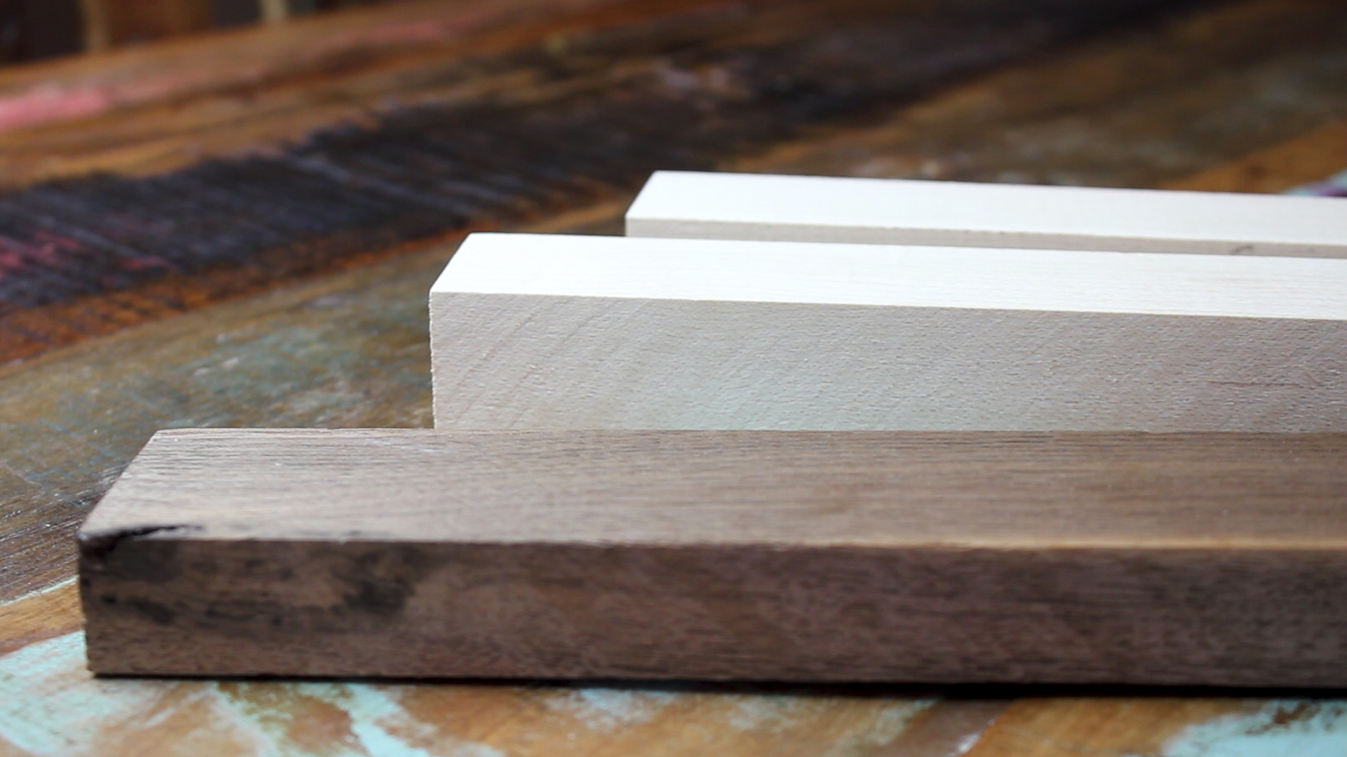
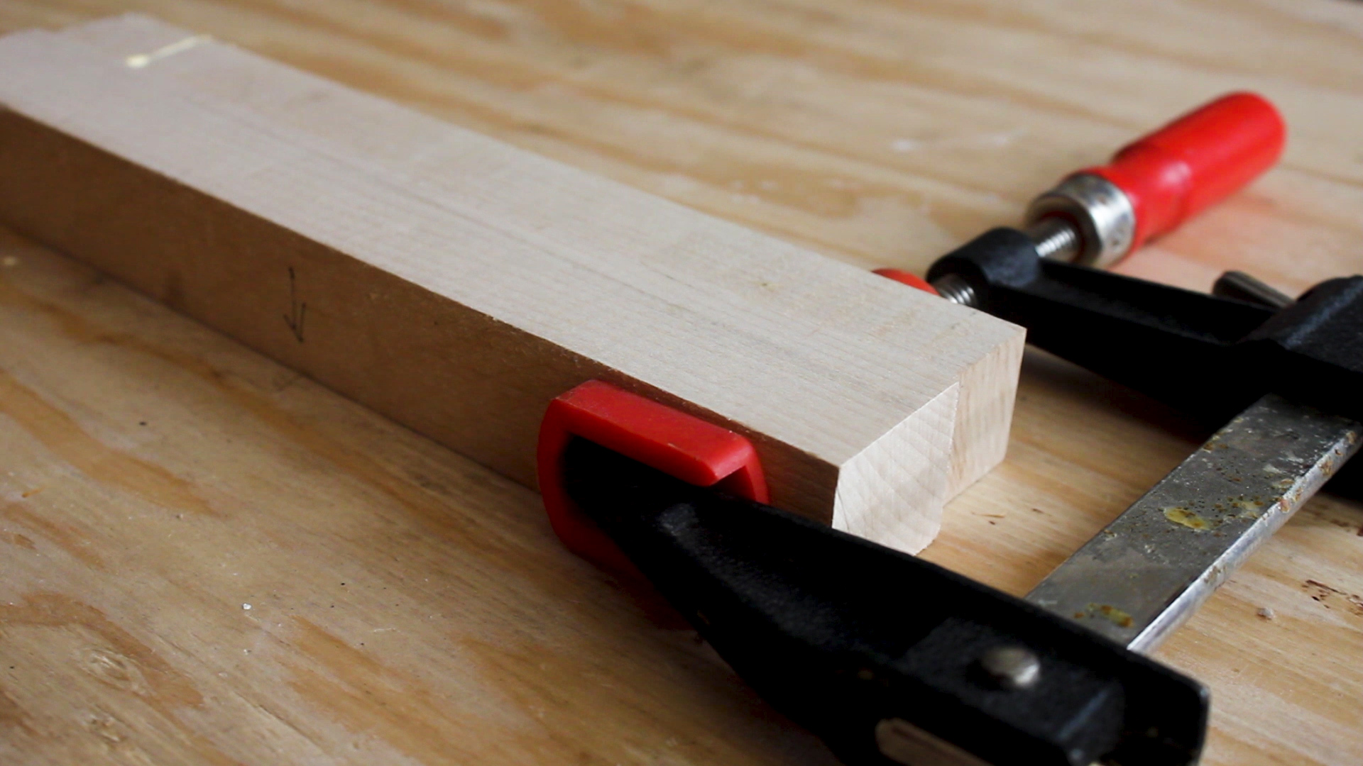
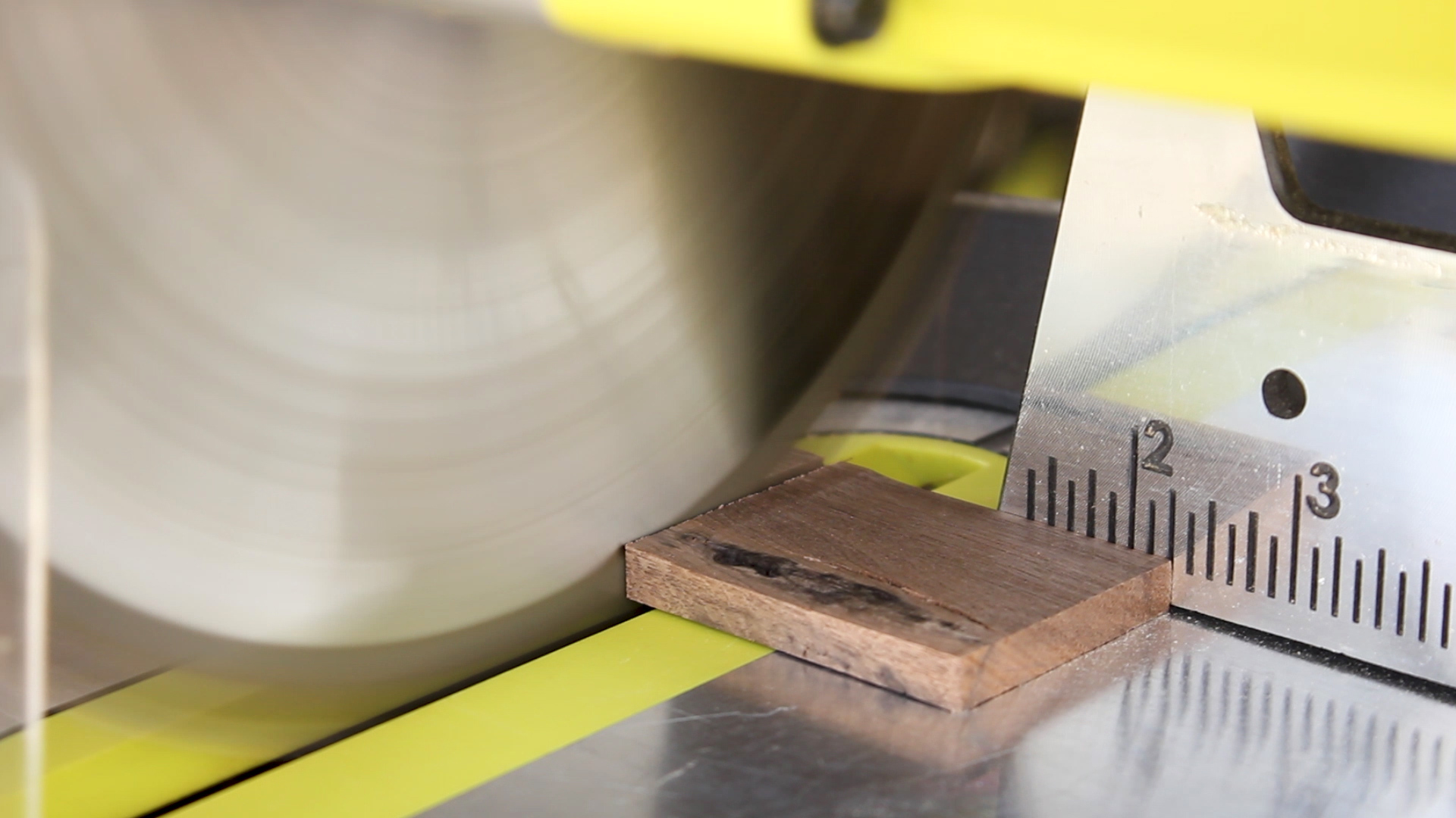
DIY Beer Caddy


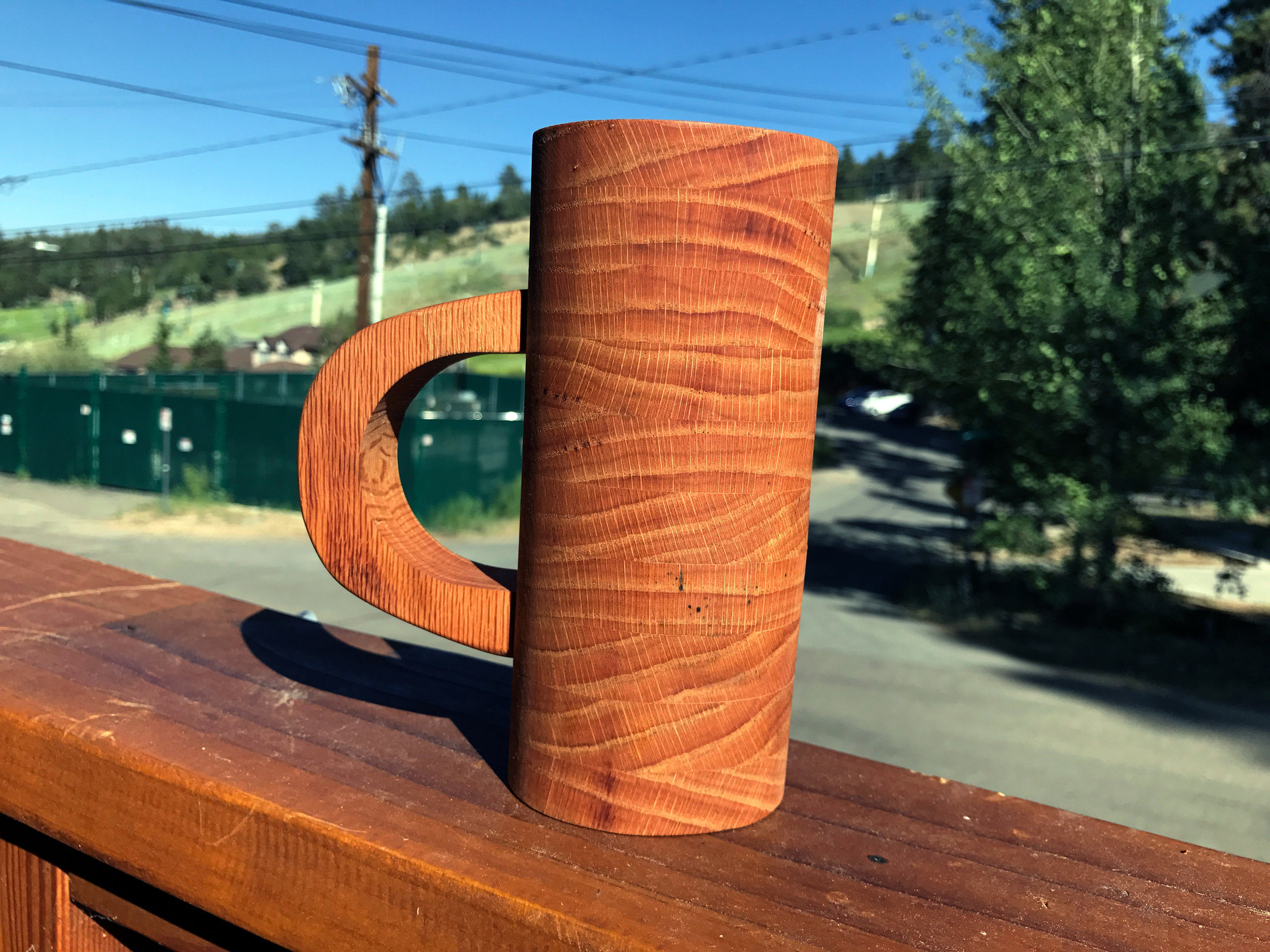
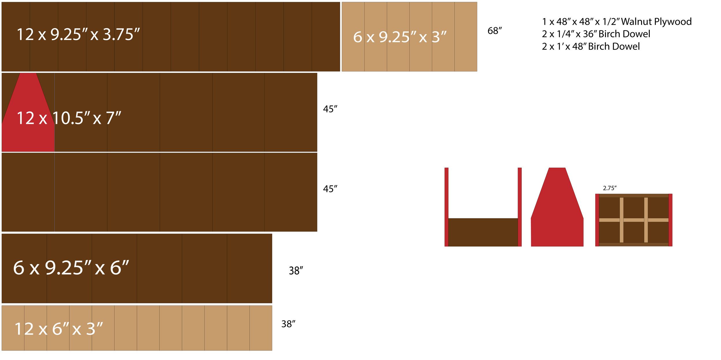
I am getting married this year, and I figured it would be fun to make something to ask my six groomsmen to join me on stage. I designed a simple beer tote that I could replicate easily 6 total times and do all from a single sheet of half inch Walnut Veneered plywood. You don't need nearly this much, and you need FAR less if you're just making one. Below is a video of how I made them, followed by designs and steps to make your own version.


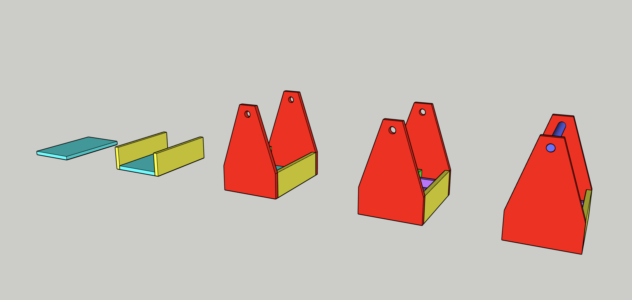
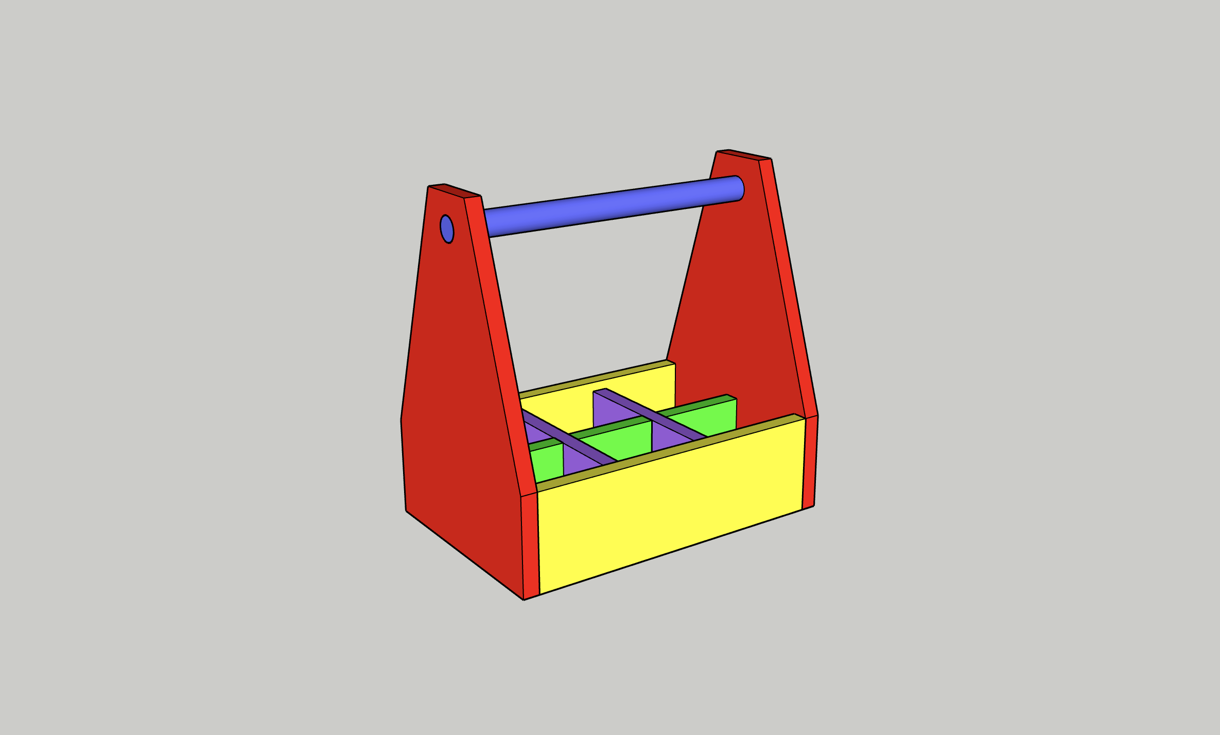
My design is very simple, consisting of four sides, a bottom, two middle dividers, and a dowel for a handle. You can scale the design up or down as much as you want (add logos, add more dowels for fun aesthetic joinery), use other types of wood - I did this way since it was a repeatable and great design with a nice aesthetic to it.

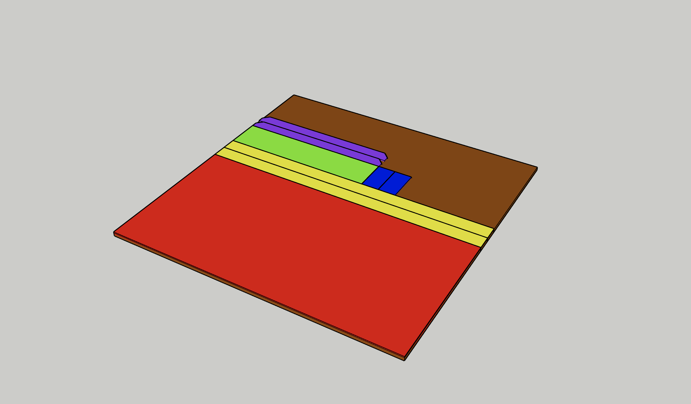
Here is a direct link to the SketchUp file - a few still images of it are below.
MATERIALS

TOOLS

FILM / EDIT EQUIPMENT

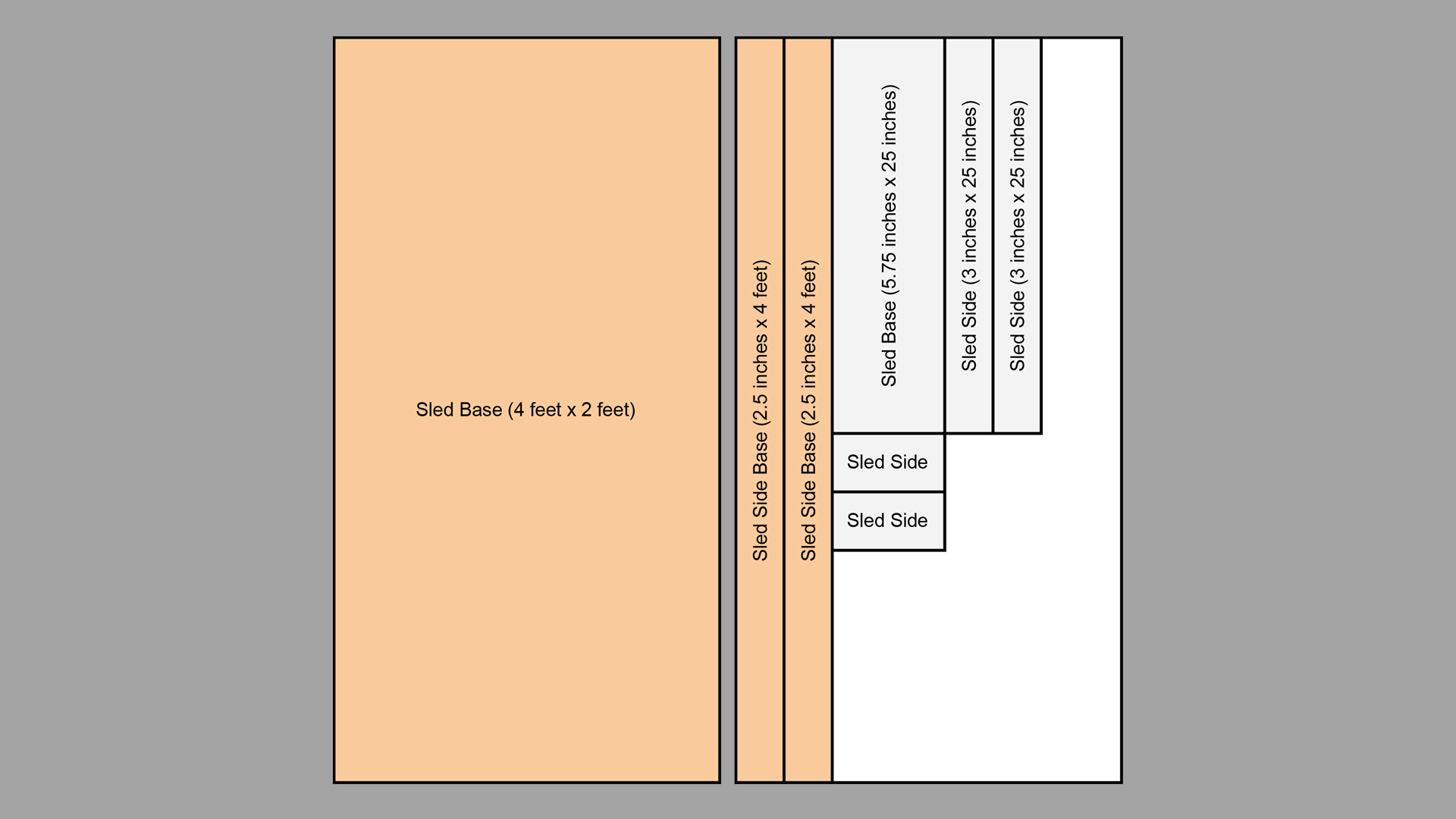
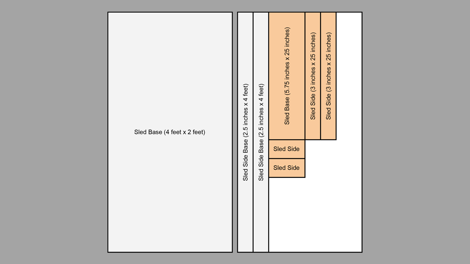
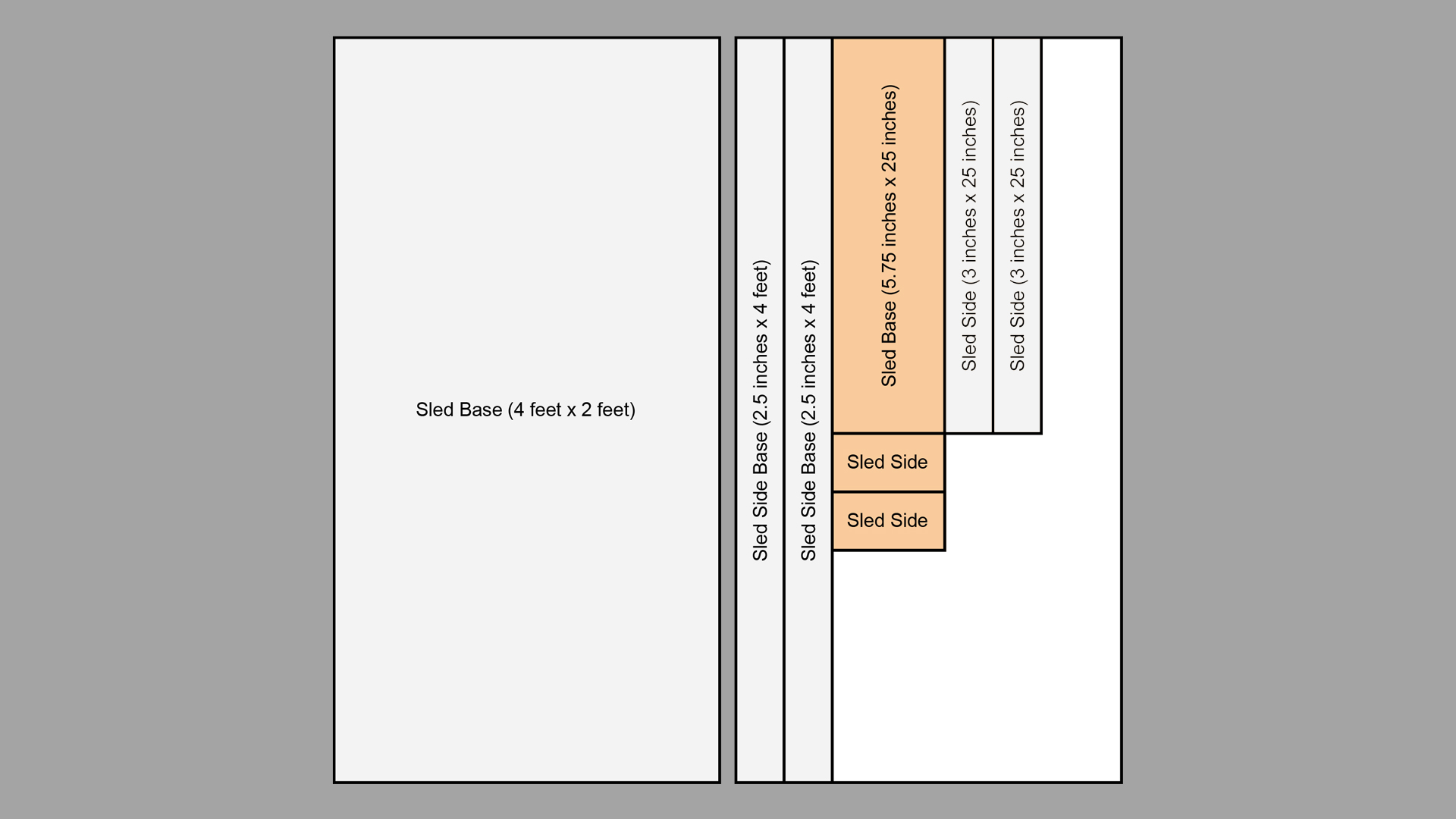
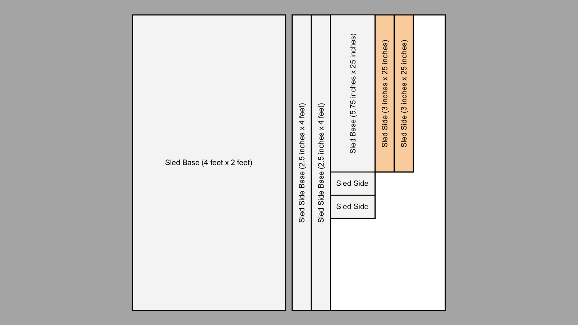
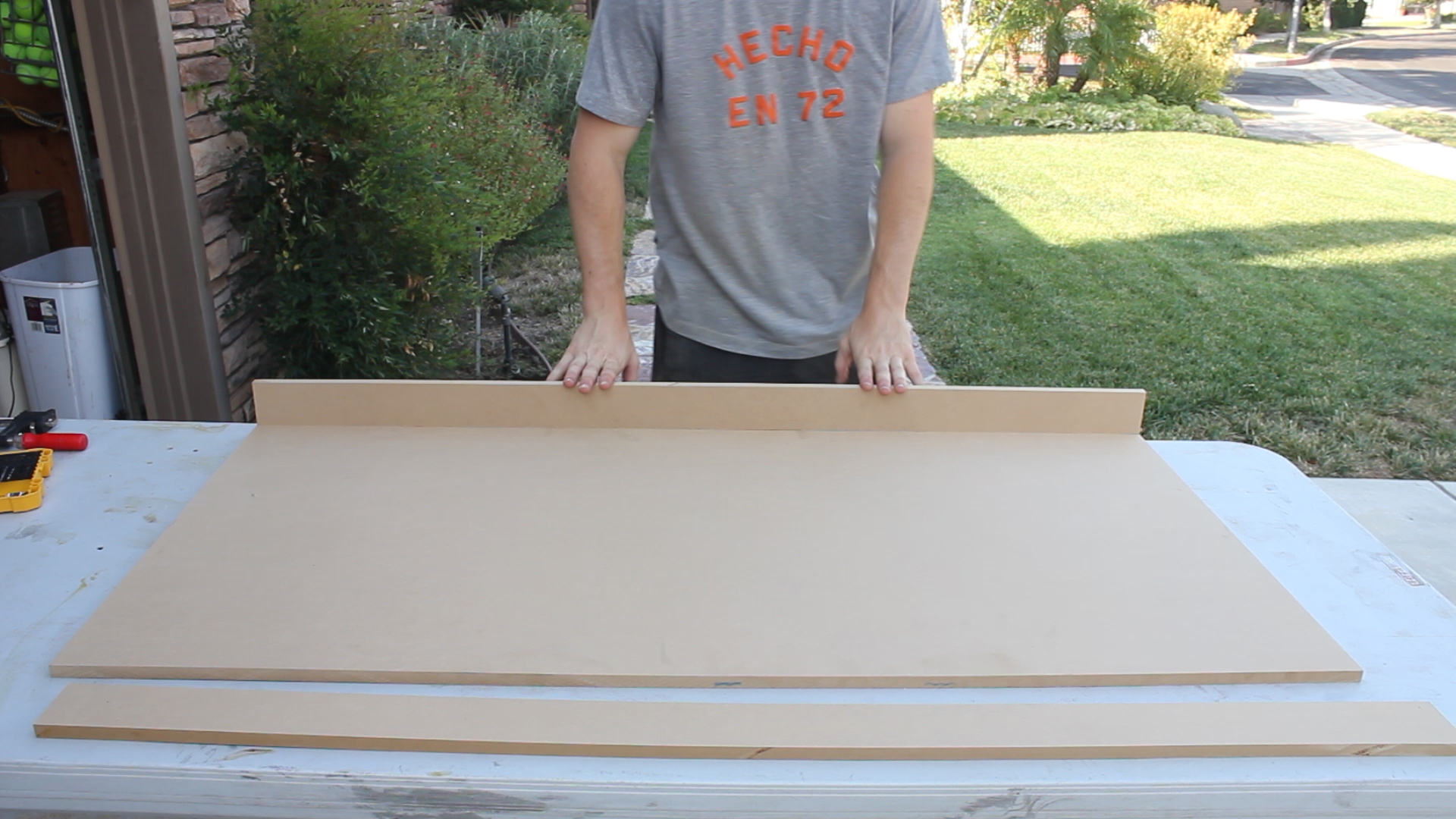
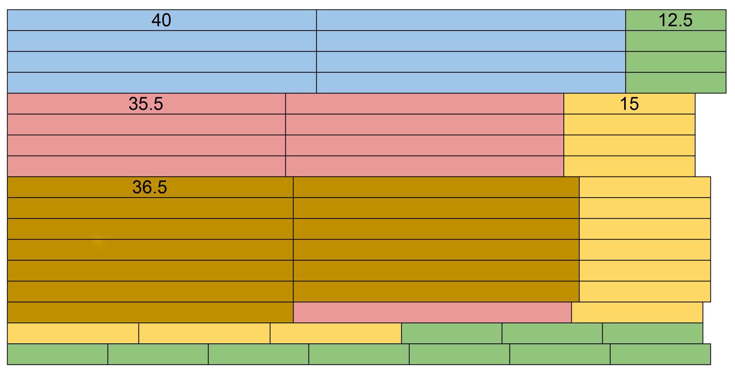
The first image shows how I designed the project to be ripped down my plywood - a design based on me needing to build 6 identical totes.

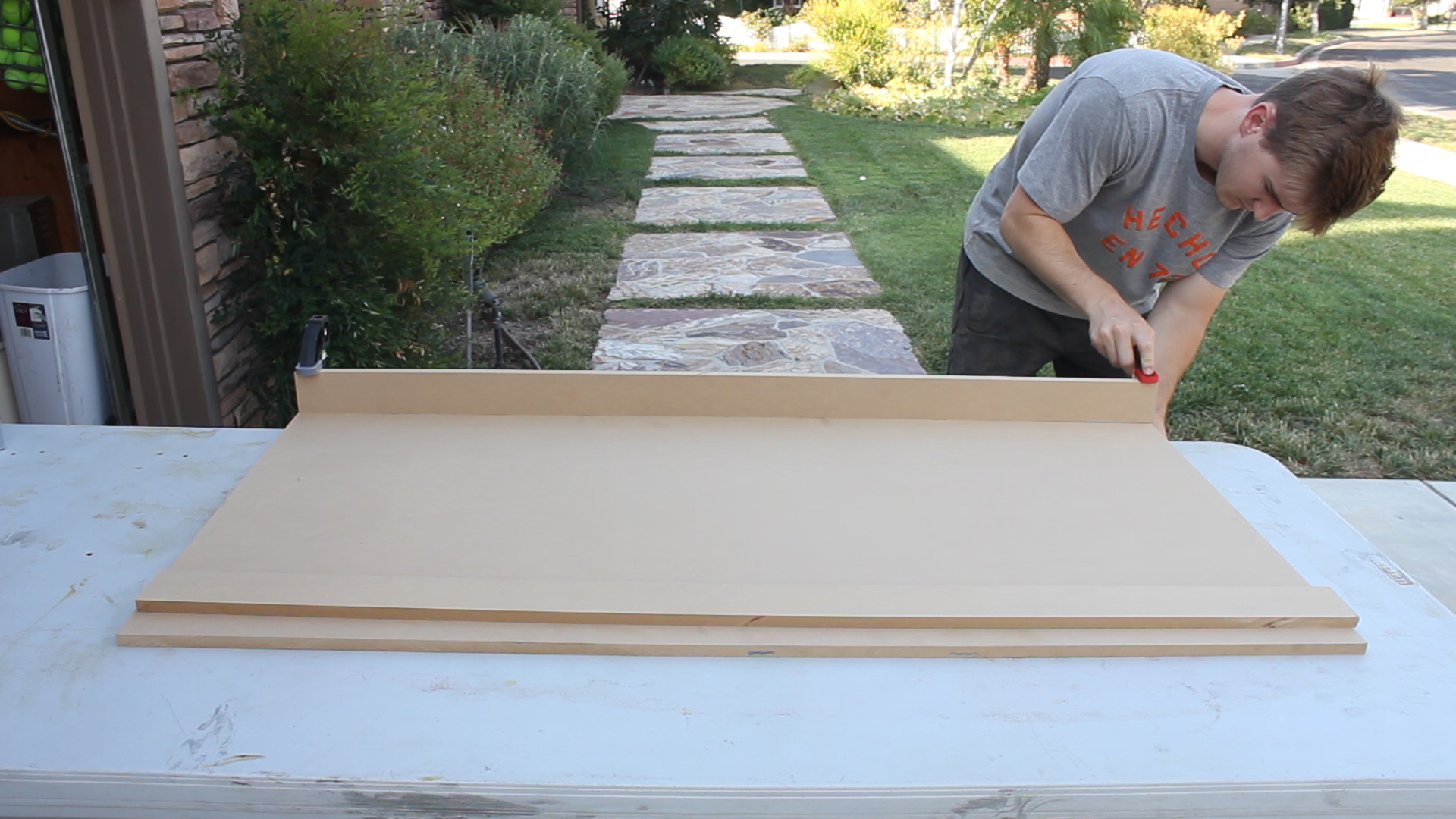
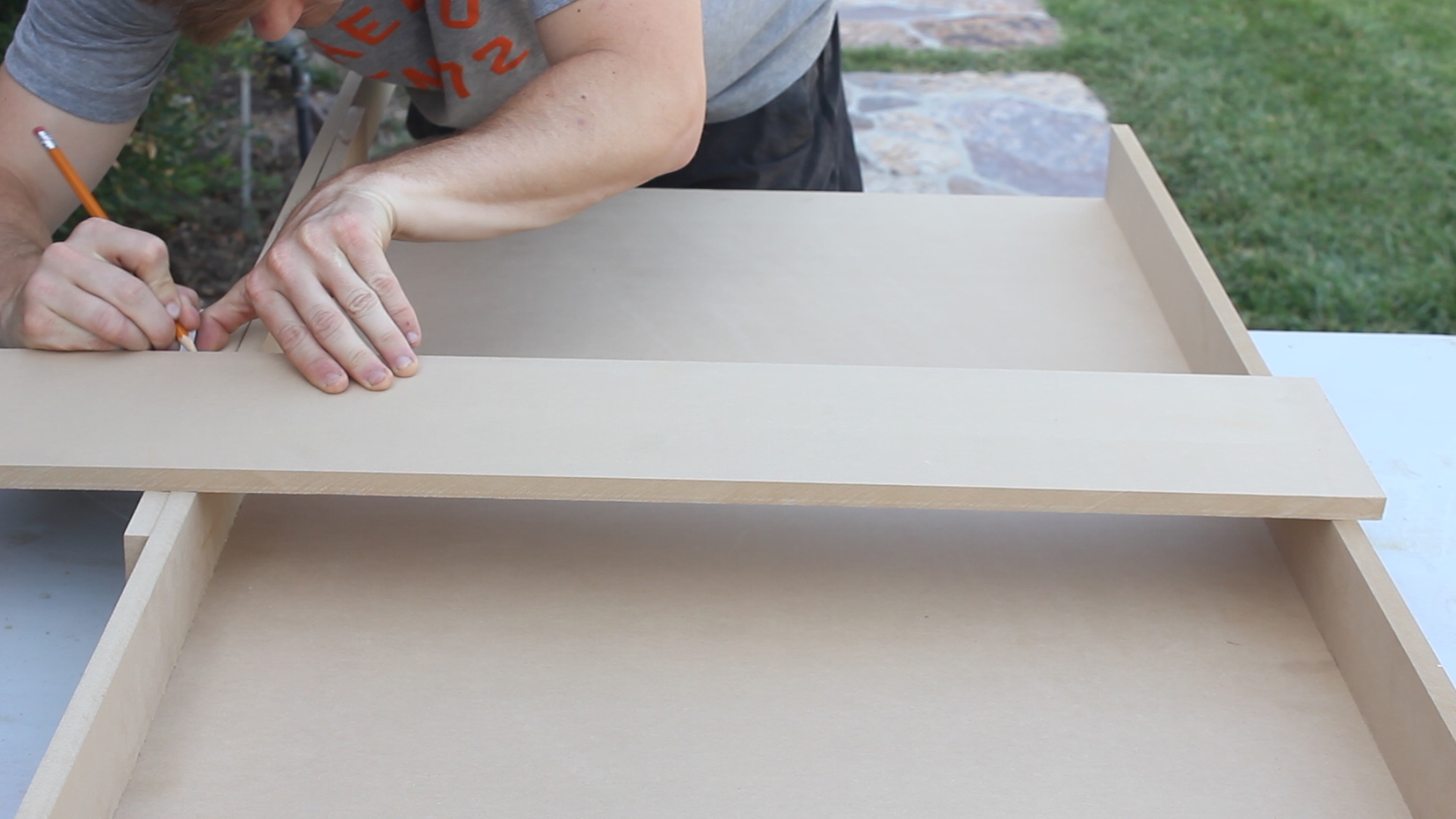
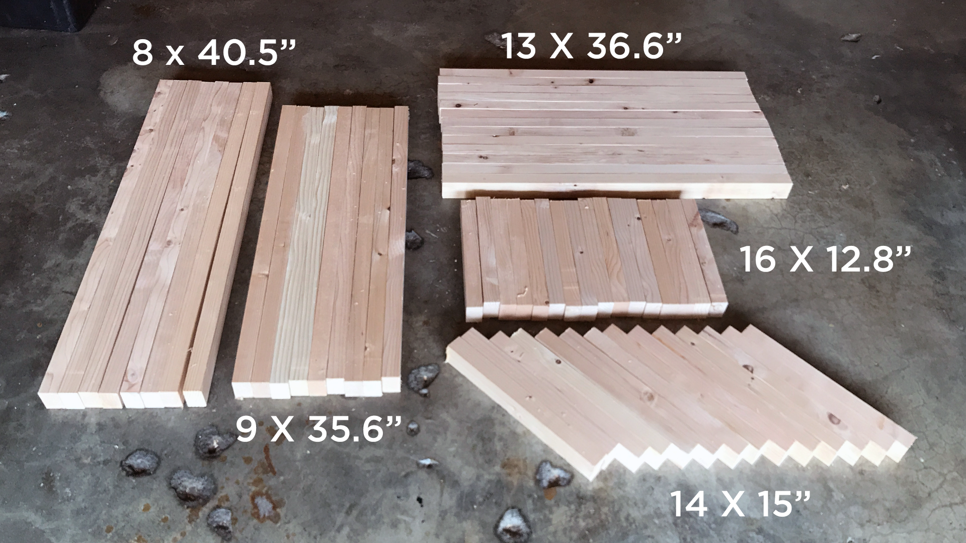
It was easiest for me to rip long pieces that I could then cut down into their final dimension on my miter saw. I used my rip cut and a circular saw to rip all of the long pieces (Pic 2), but you can do this on a table saw more easily if you have a bigger set up or partner or just use a straight edge. Pic 3 just shows the pieces stacked.

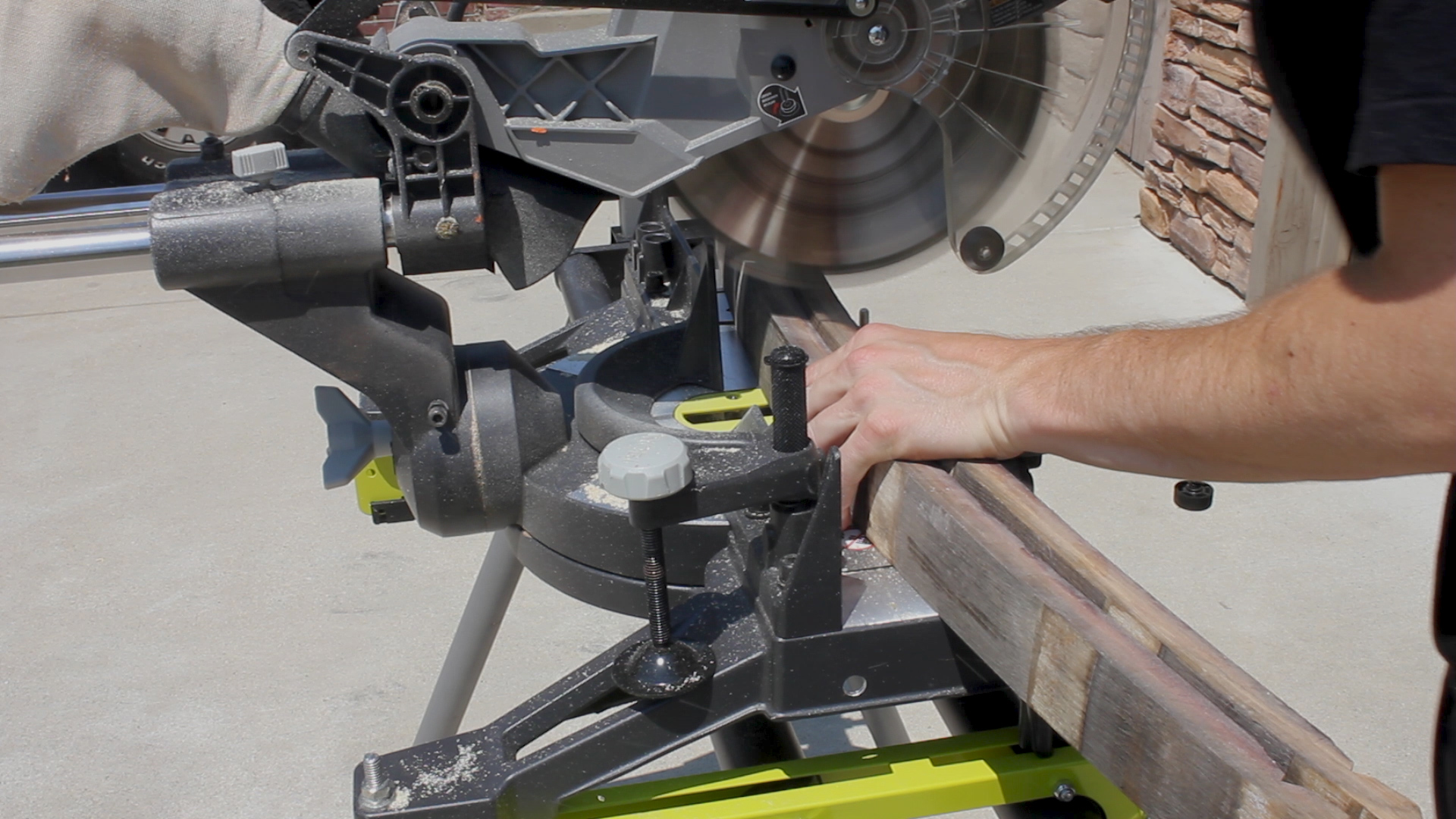
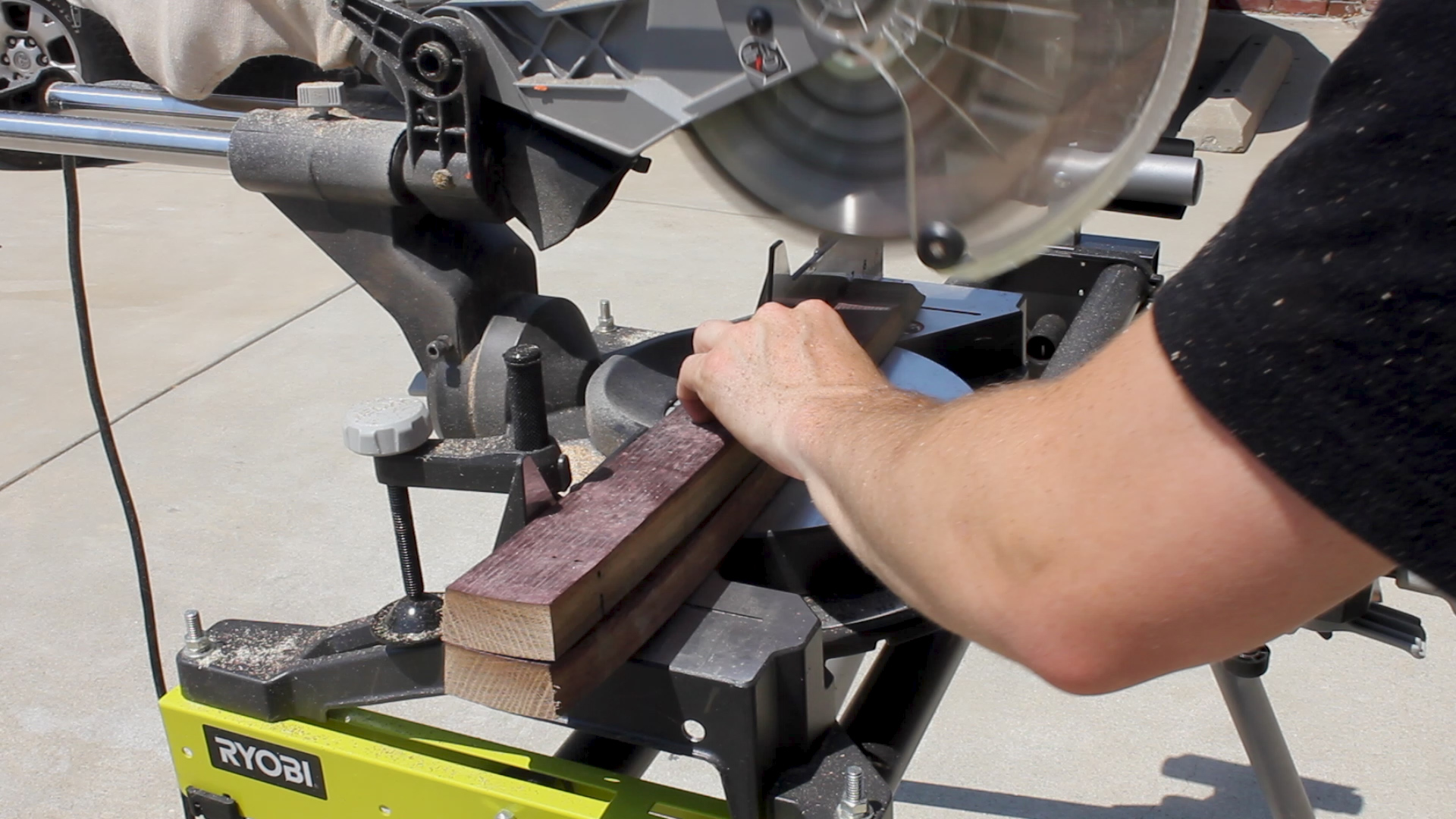
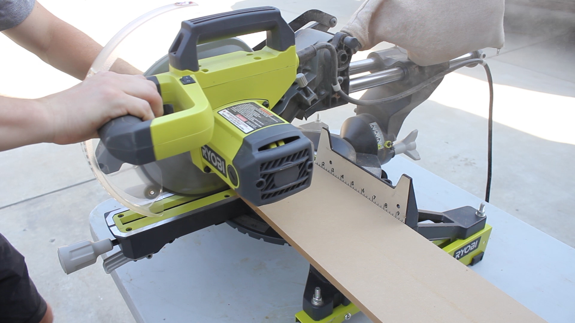
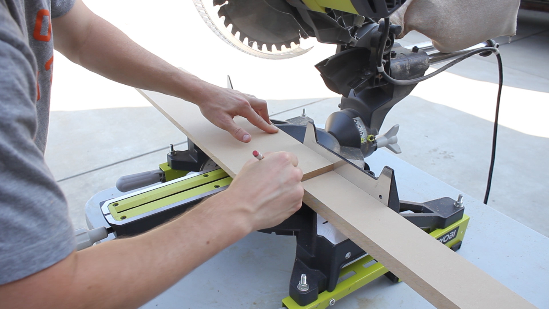
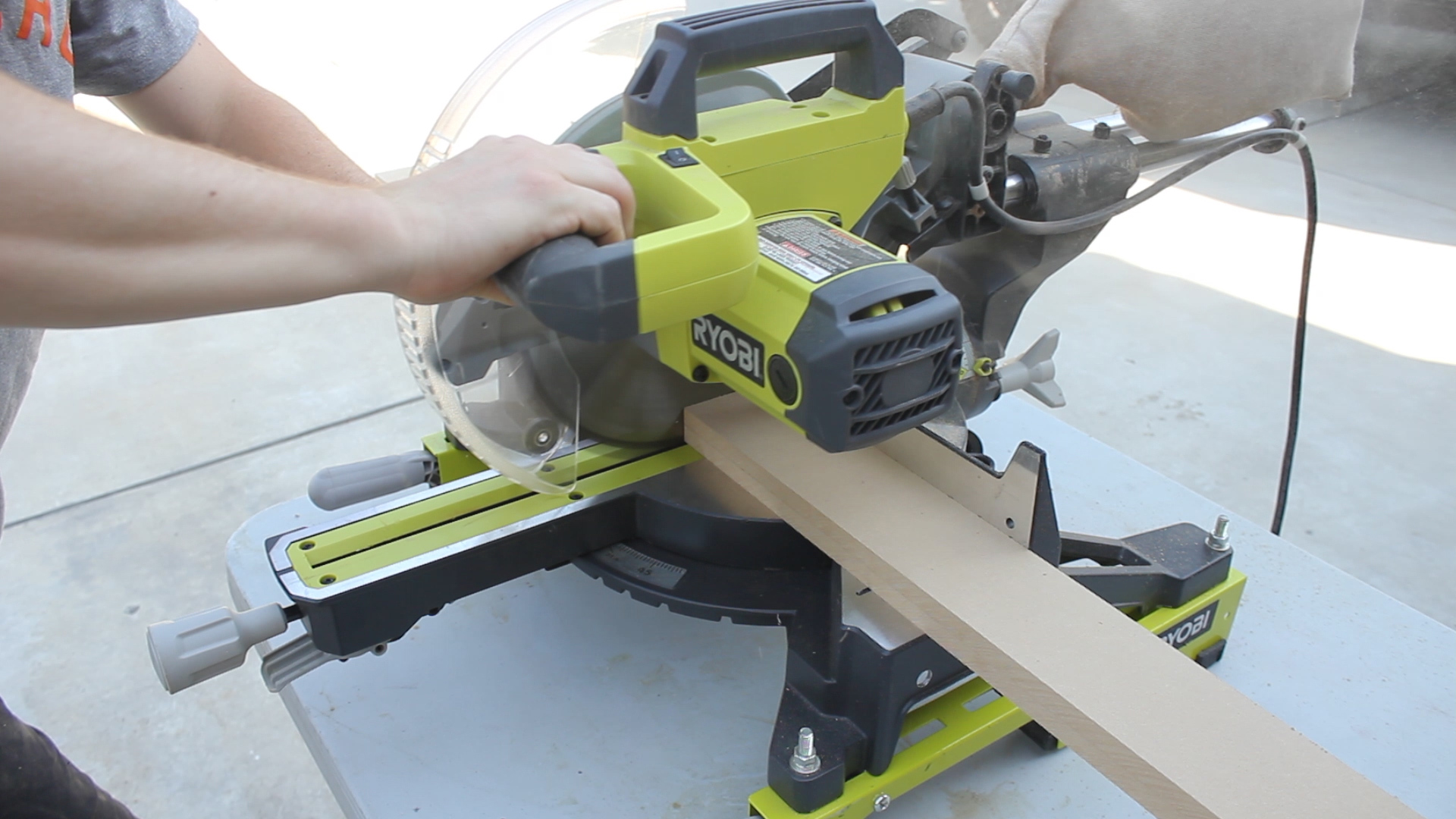
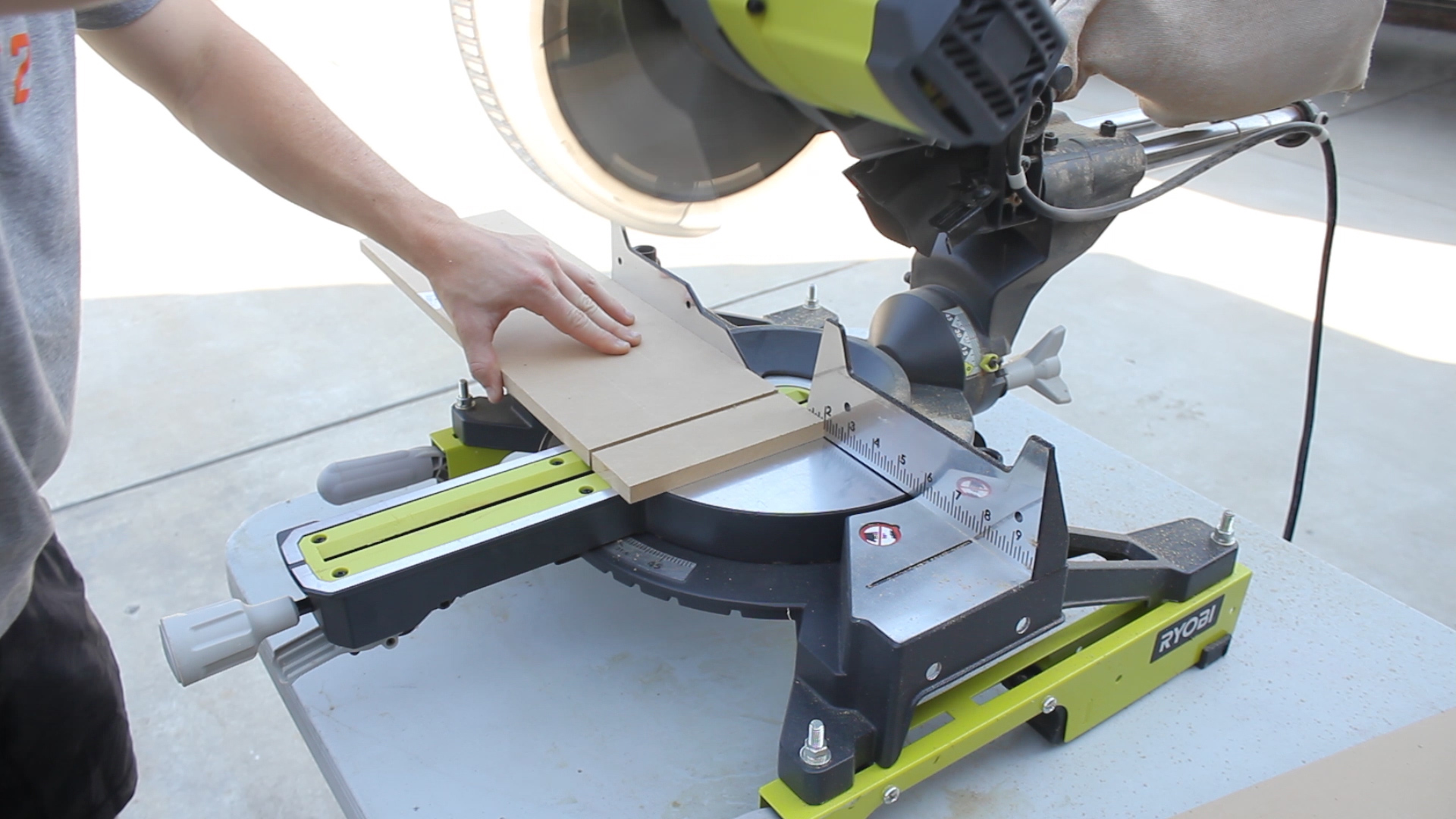
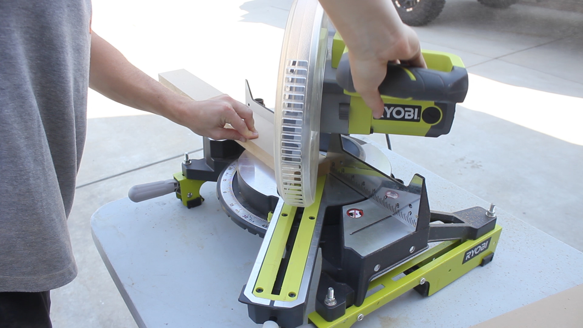
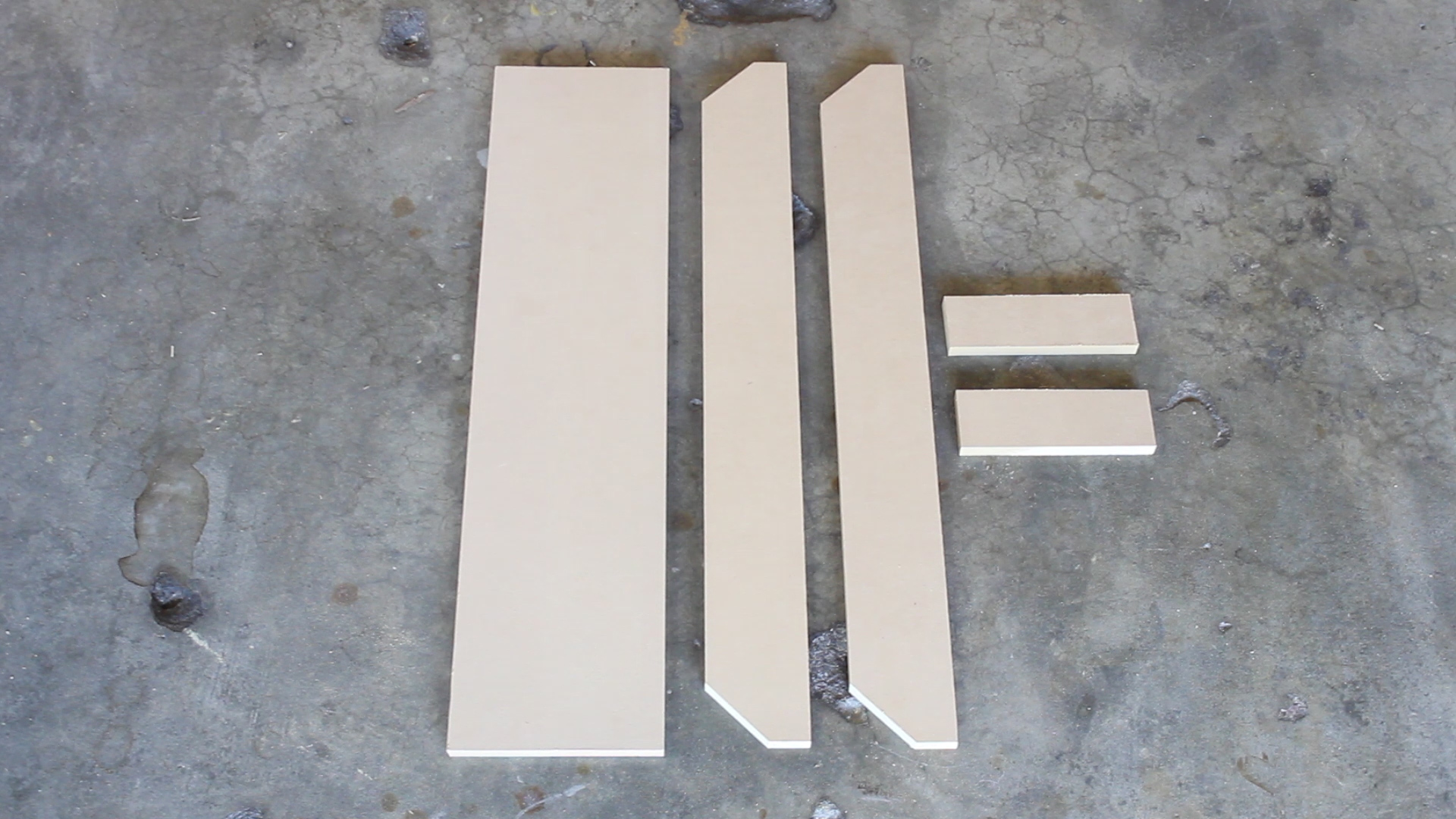
I set up stops on my miter saw (Pic 1) to rip down all of the various pieces (you'll see all the cuts in the next step). One final cut to do was to make angled cuts on the two end pieces so that they formed pentagons (Pic 2). I needed to do this for a total of 12 cuts (6 totes x 2 end pieces for each). I cut away the excess triangles on my miter saw in Pic 3 - it was easiest to cut six pieces at once to get one side, then flip the pieces over and make the same cut on the other side individually.

NOTE - The design of my cuts had all four of my outside walls going to the ground, with the base of it being sandwiched between all four pieces, versus the base piece being the entire bottom and my four walls resting on top if it (if that makes sense?).

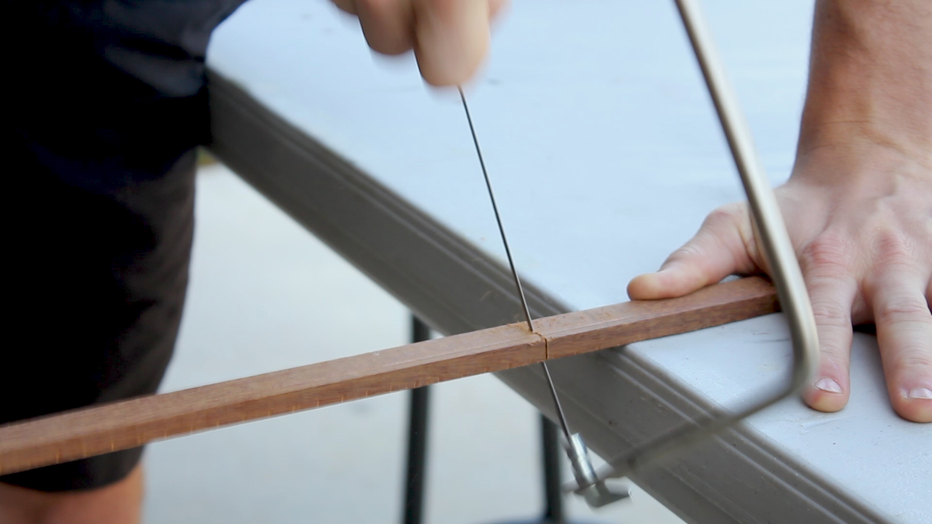
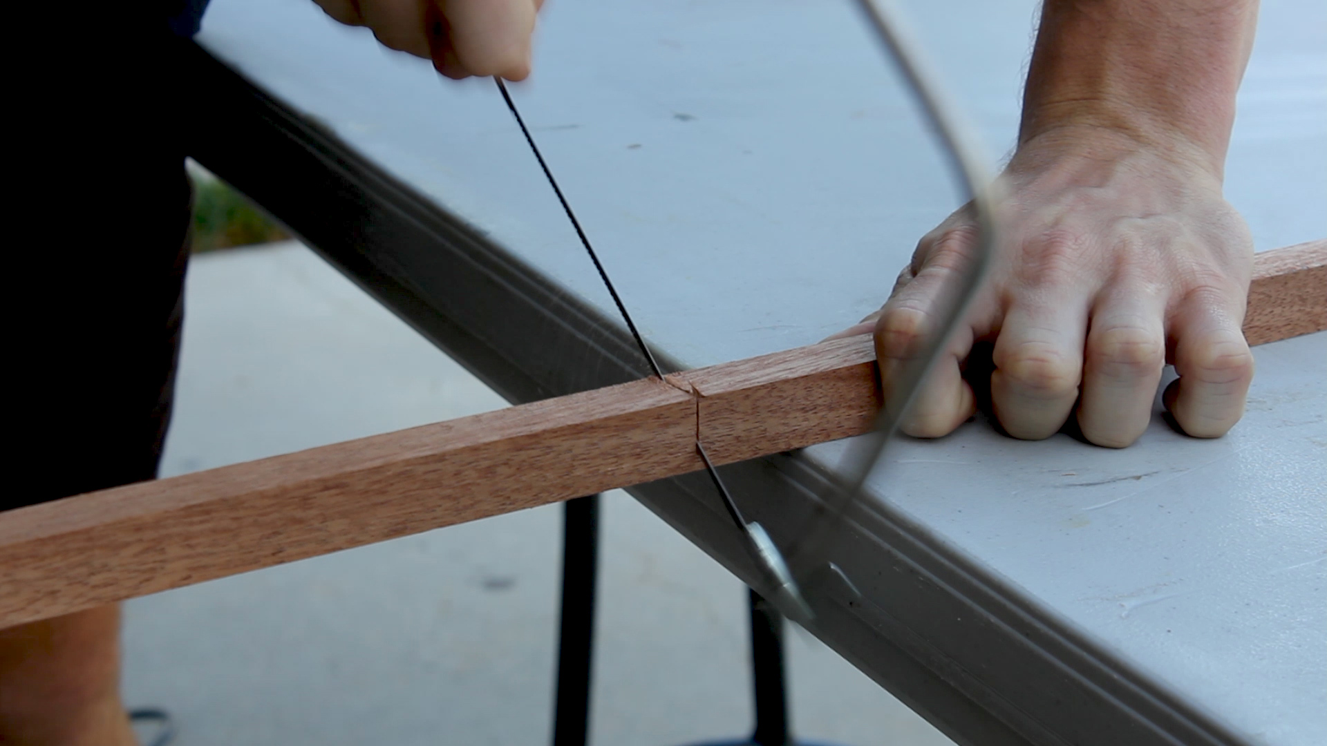
Pic 4 shows me cutting the dowel lengths - which were the length of my tote + 1" to account for the width of the two half inch ends.

13.jpg

Pic 1 shows how I would take my three middle pieces and combine them to form a single piece that divided the tote into 6 quadrants. To do this, simply cut dados halfway into each piece so that they can fit together snuggly.

Most, if not all miter saws, have stops in place that you can set (Pics 2-3) so that you can make cuts to a certain depth. I measured out how deep I wanted to cut into my pieces, set that stop, and then packed together my pieces to make repeatable cuts until I had "hogged" out the right amount of material (about 1/2" wide to match the plywood thickness) in Pics 4-5. You can also do this with a band saw if you have one or a jigsaw (which might be messier).

One thing to note is that when you do cuts that don't go all of the way through, you'll want set up a throw away piece in the back (You can see it in Pic 5) so that you can push your saw blade all of the way through and get an even cut. Hard to explain, but makes sense if you try it.

Pic 1 shows all of the cut pieces for my 6 caddies.

Pic 2 shows the pieces necessary for A SINGLE TOTE and the dimensions I used. You can see dado cuts in the bottom right pieces that I mentioned in the previous step.

Pic 3 shows me just lightly sanding the outside edges of my pieces. Veneer is very thin and you can sand through it easily, so make sure you only do a very light pass (if at all) when you do so.

I measured out (Pic 1) and drilled a 3/4" hole on each end piece that would accept a 3/4" dowel.

I used a 3/4" spade bit for this and my power drill, but you can use a drill press if you'd like and/or a Forstner bit to help make more repeatable cuts (Pic 2). The important thing here was to keep it even and clean and prevent tear out on both sides. You can use tape or if you do have the drill press this might be easier. However, without those, I found the best way was to drill 2/3 of the way through the piece, then flip it over and use the small pilot hole to drill from the other side. Pic 3 shows how cleanly the hole would come out.

The holes were very snug and I ended up not using glue to secure the dowel (you obviously can if you want to).

Pics 1-4 show me assembling all of the pieces before glue up to make sure it all fits together.

I was 99% sure if would, but you never know...

You can see how my four outside walls go all of the way to the bottom instead of sitting on top of the base - this was a design choice.

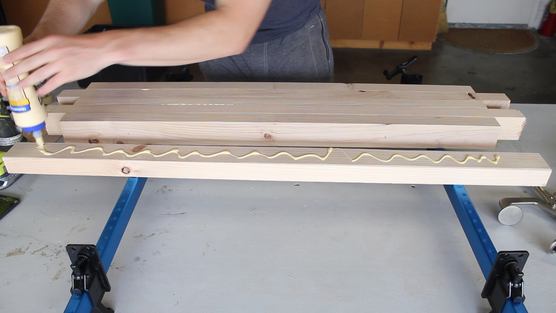
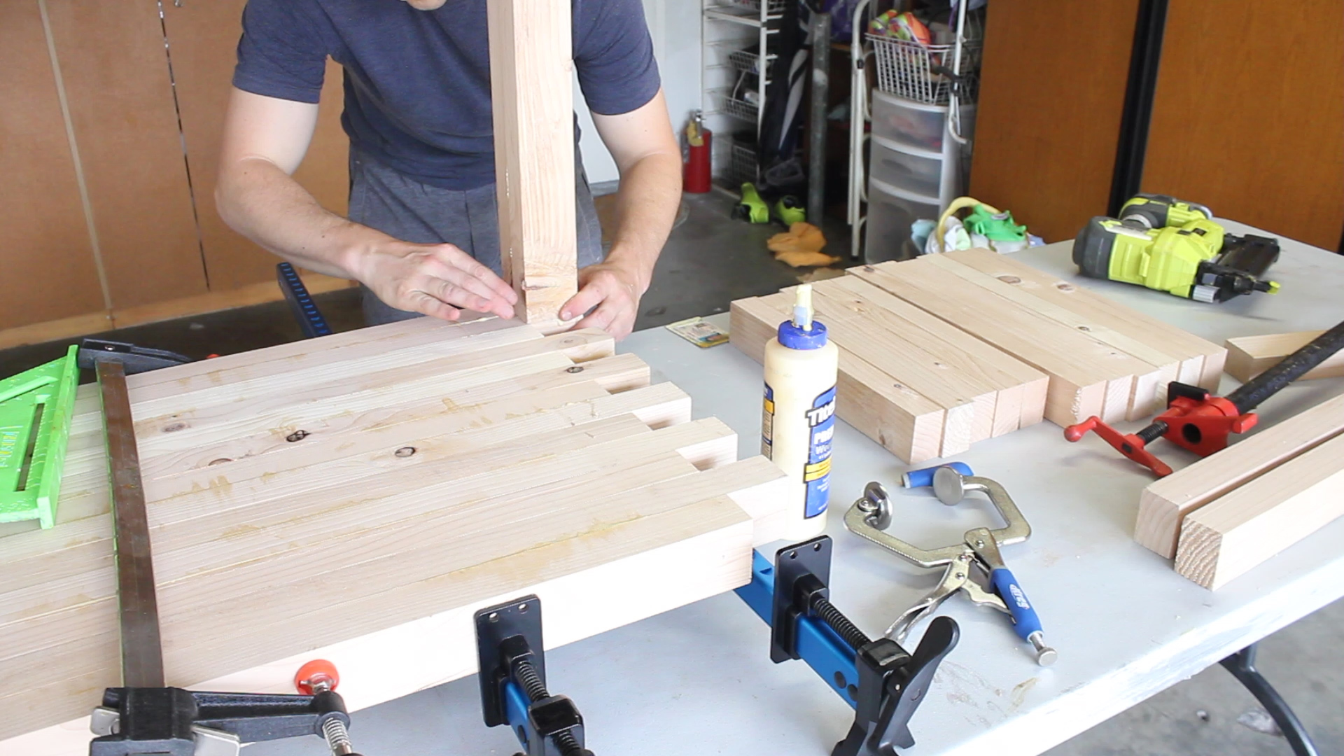
I then glued up all of my pieces in Pics 1-3 using wood glue.

Few tips / notes here. Wood glue is plenty strong enough to hold this together, but you can add pin nails or dowels, etc. to help hold it together.

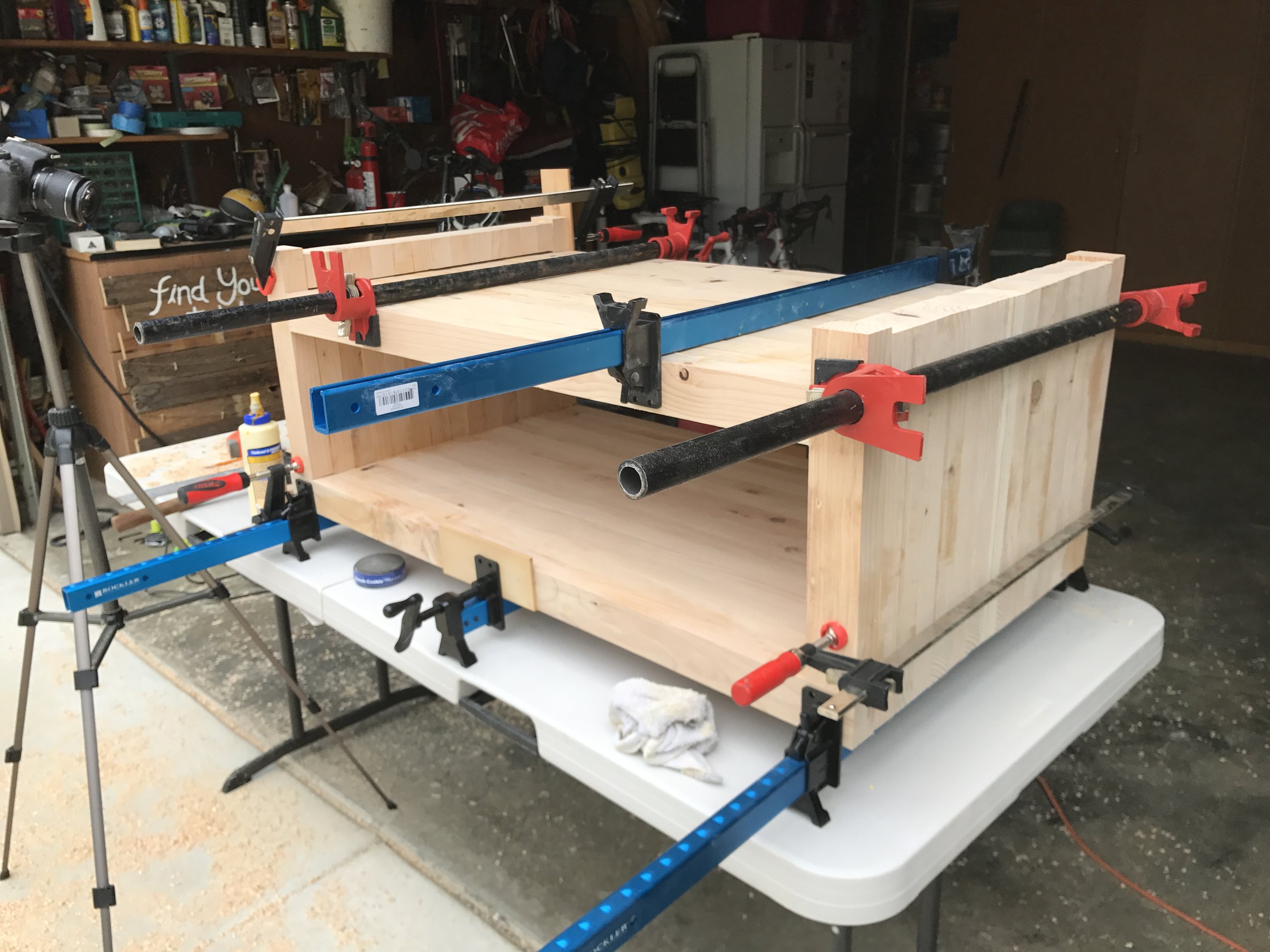
I recommend four squeeze quick clamps to hold it together while it cures for about 2 hours (Pic 4).

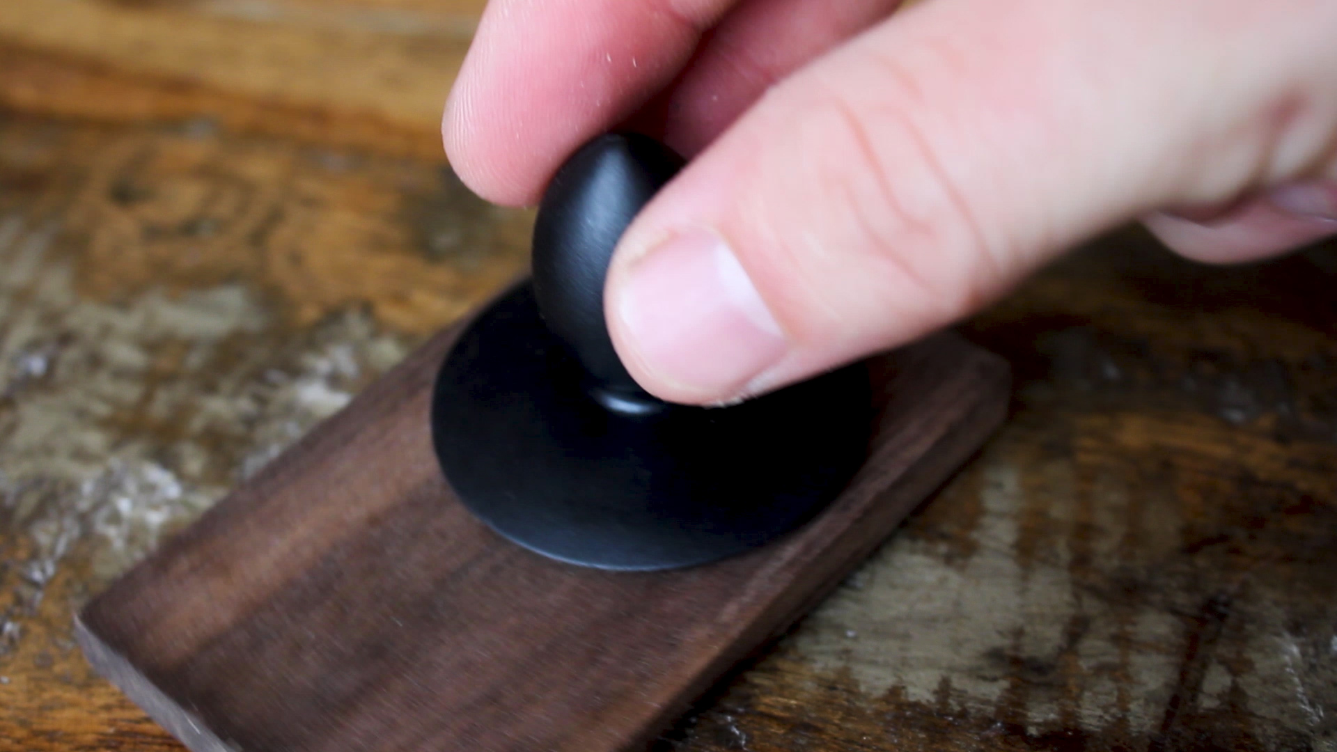
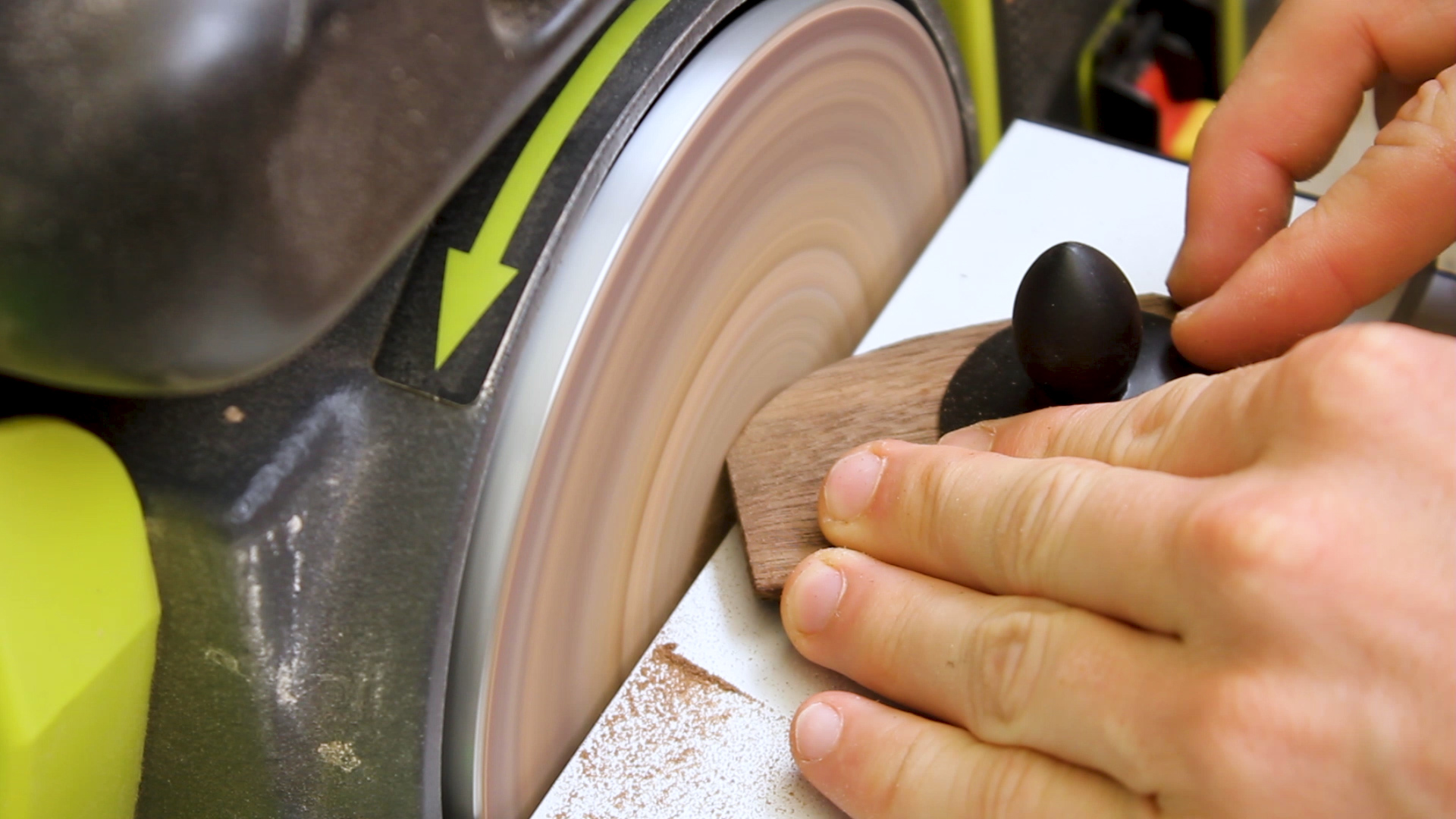
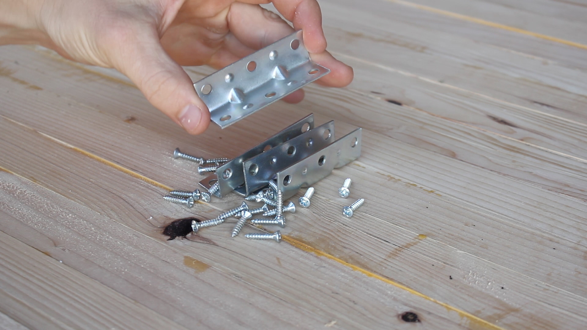
I bought $5 cast iron bottle openers (Pic 1) that you mount to a wall usually to attach to these. They also came with screws, but they are too long for the thickness of the material. You could cut them down, or just get smaller screws.

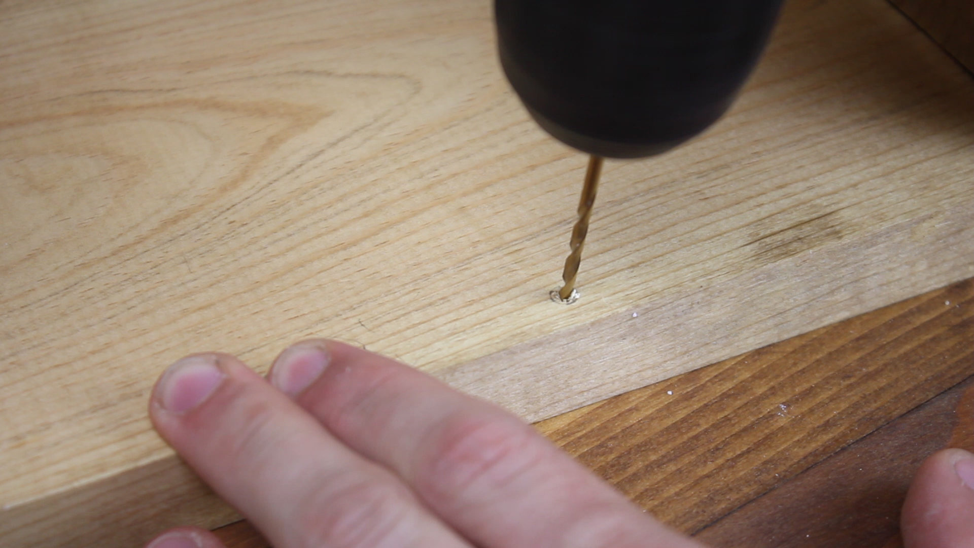
I don't have a means to cut screws, so my solve was as such: pre drill holes (Pic 2-3) for the two holes, with the bottom hole not going deeper than the thickness of the plywood, and with one that would go straight into the dowel so depth was not an issue. This also would allow the dowel to be further anchored to the tote (not necessary given the snug fit, but it only helped). Use a single smaller screw (Pic 4) that was smaller than the 1/2" thickness of the material.

These felt very secure to the final tote.

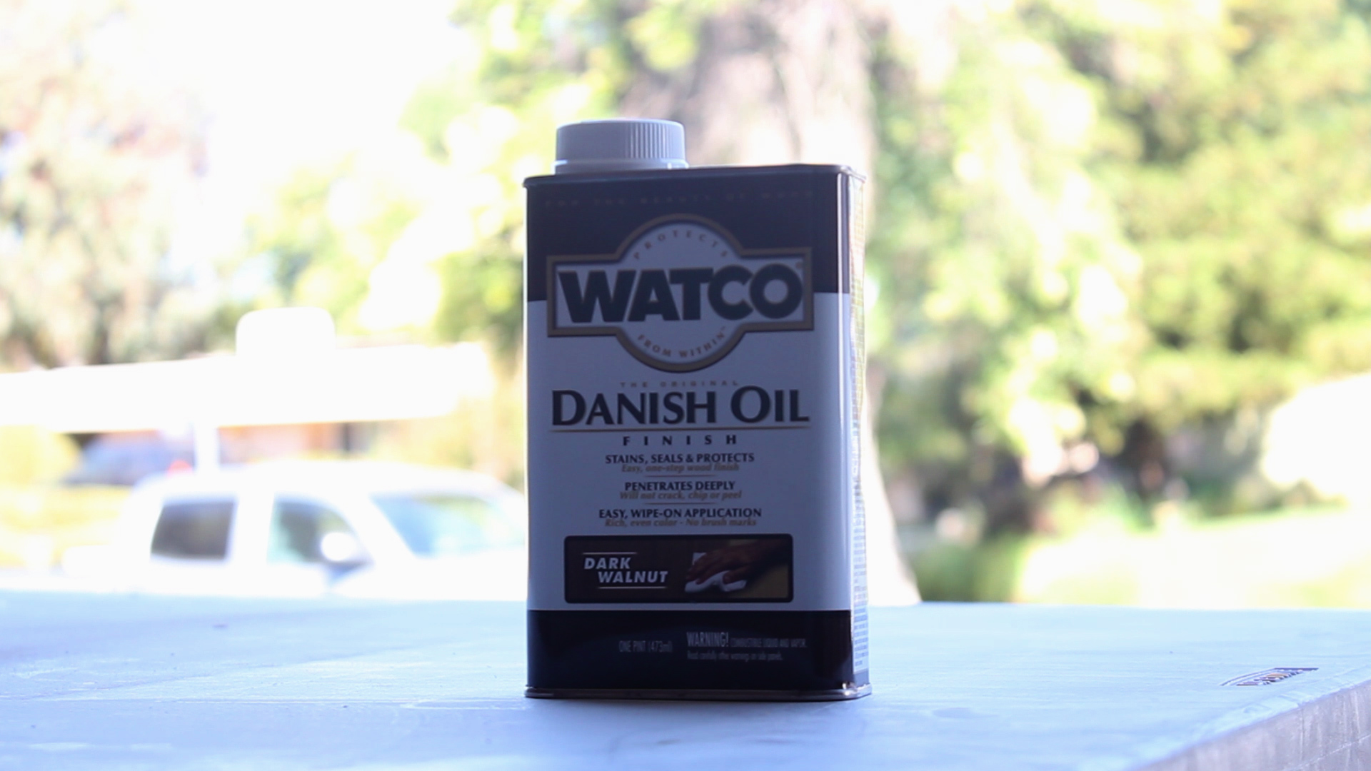
Now, I am very happy with how these came out - attached are some final photos for you to check out. I did go back and add some cutting board oil to them to bring out the grain (check out the video for that step!)

They look great with the walnut veneer, are very simple and easy to make (and could be with just a circular saw and drill), and will make awesome final gifts for my groomsmen. I think making six of them made me take a simpler approach, but if you just want to make one, then you will have much more time (and energy) to focus on making your design unique.

A few ways you could improve / change the design:

  • Use some sort of bleeding ink technique, stencil, or laser cutter to add text personalizations to each

  • Use a finish to bring out shine (I personally don't think it is necessary for these types of things)

  • Use other wood variations to make them appear more rustic or "thrown together"

  • Use additional types of joiner to make contrasting colors pop (dowels for joinery, etc.)

  • Alter the design to be something more specific to your use

As always, thank you for reading! I would be so grateful if you could please subscribe to my Youtube Channel for future projects. Thank you again to Purebond Plywoods for hooking me up with materials for this project.

I put out videos every few weeks.

Cheers! Zach


Convert Shop Storage to Whiteboard Surfaces


I acquired two 5.5' wide red oak cabinets from a house that just had their kitchen remodeled. They are only 12" deep and make them ideal storage for a garage shop as you don't have to sacrifice a lot of shop space to create a lot of surface.

I wanted to add whiteboard space to my shop for a host of reasons, but didn't want to sacrifice open wall space, so I came up with a quick and easy solution to repurpose these shelves as new whiteboard space. Check out how I did it here:

If you don't have old cabinets, you'll have to go the old tried and true DIY method of actually building some shelves - this can work to your advantage as you can make them more bespoke to your space, add storage, and add whiteboard space.

My cabinets have sliding doors. If you don't have cabinets that have these types of doors and you don't need to make new ones, you can also look into whiteboard paint!

MATERIALS (Assuming you already have shelves)

  • 1 x 4' x 8' x 1/8" White Hardboard (about $13 at Lowes / Home Depot)

  • Shallow cabinets (can be made from 3/4" plywood!)

TOOLS
Sawstop

RYOBI

You can just as easily get away with a circular saw for this project instead of a table saw - it's just that simple.

My cabinets were red oak - which I find pretty ugly - so I painted them. One coat of primer, two coats of paint I used on my kitchen remodel. Above is a photo of me pretending to paint.

5.jpg

Remove your cabinet doors (probably do this before painting) and measure their length and width - grab assistant for this if needed.

6.jpg

Using a table saw, circular saw with a straight edge, or a track saw, cut down your white hard board to proper dimensions. I have a table saw so this took about 3 minutes total - white hardboard cuts very easily but is very strong. Test to make sure your cuts fit (and crack a smile!).

You'll need holes in each door to insert your finger to slide open. I used a scrap piece of plywood to mark and measure a hole the exact same distance inward from the bottom and side and used my punch to mark a hole. I then repeated this process but on the opposite side for the sister cabinet.

My cabinets were divided into four sections, each with two sliders, so your holes should be in the same position but mirrored so they both end up on the outside. Then I used a 3/4" forsner bit to drill out holes - again this drills very easily.

Now you can just mount your new sliders and have a ton of whiteboard space!

I love these - it is SOOOO simple in design but so practical in function. It took me a few days to come to this solution, so I hope sharing it with you on this website helps spark some ideas on how to make your shop more efficient.

So far, I've used the panels to list out future projects, steps for projects mid-build, and then post production needs on my videos.

Thanks for reading - make sure you check out the video in the first step on my YT channel!

See you around!

Zach


DIY Wooden Tablet Stand

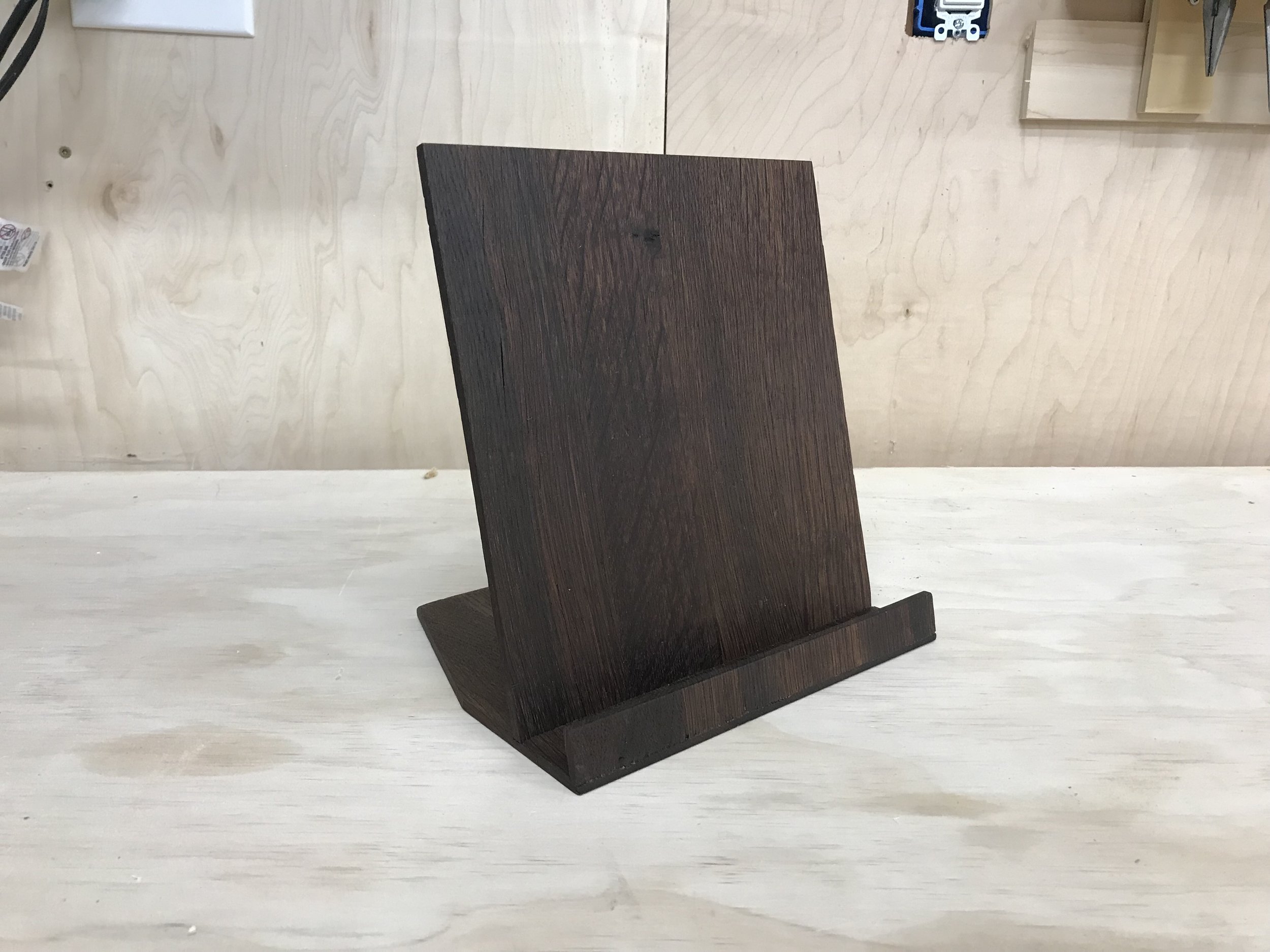
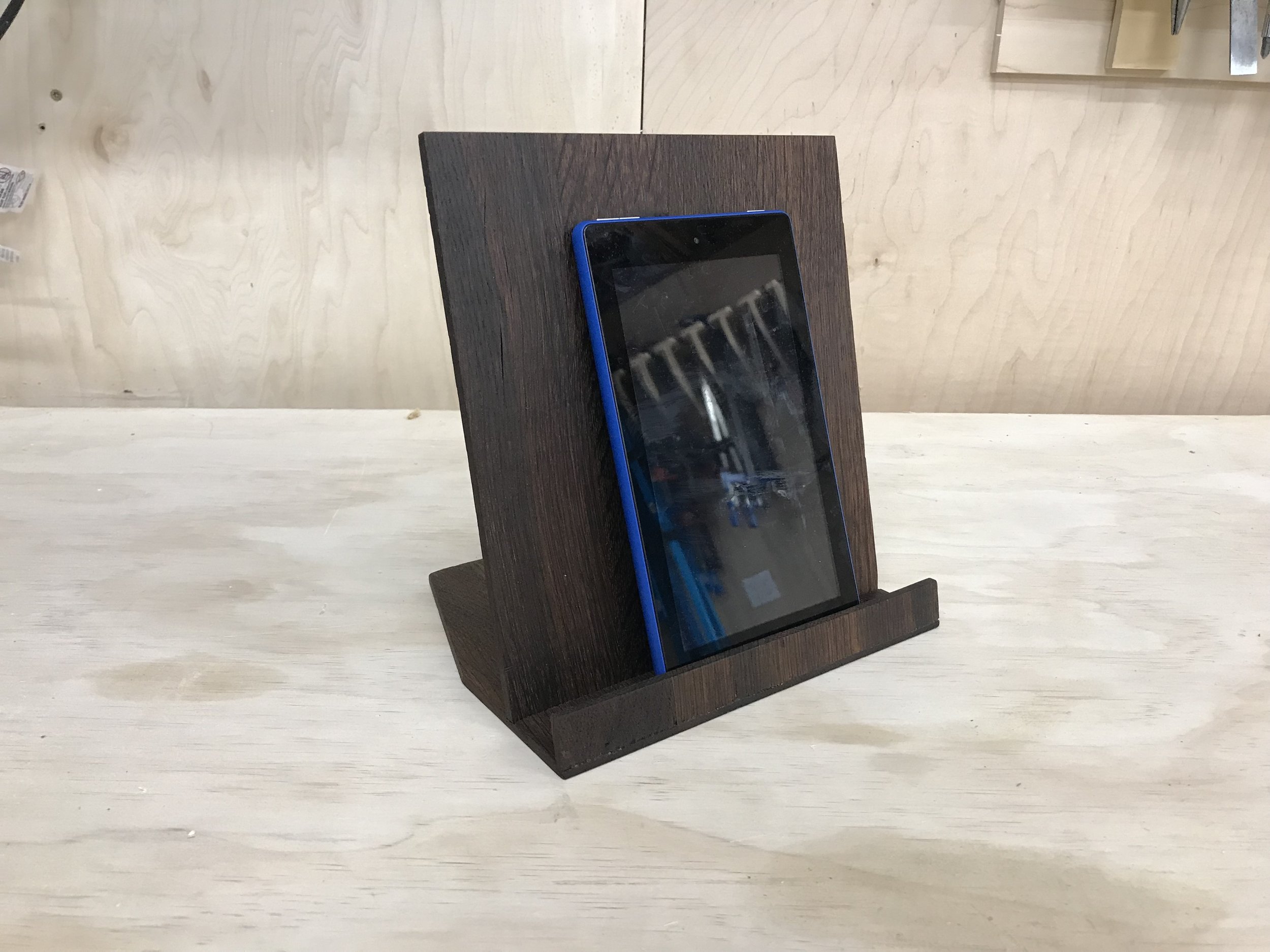
For my fiancé's bridal shower, she received a Kindle Fire tablet for the kitchen. She had been wanting one of these for some time now - as she can use it for recipes, to watch shows, to set timers and alarms, etc. Now, she needed a proper stand for it, so I decided to tackle the project on a whim with some wine oak wood I had. Below is a video of my build, followed by full instructions, including materials and steps.

Below are all materials and tools for the project. Note - if you have thin strips of hardwoods - you can get away without using a planer - you'll just need an orbital sander to flatten and smooth after glue ups.

MATERIALS
4 x Oak Slats (about 3 feet long, 1/4" thick, 2.5" wide)
TiteBond II Wood Glue: http://amzn.to/2peRFus
Mineral Oil: http://amzn.to/2p1hu2N

TOOLS
SAWSTOP
SAWSTOP Contractors 30” Saw: https://amzn.to/2Luh91q

RYOBI
10 in. Sliding Compound Miter Saw: http://amzn.to/2q1klHw
Miter Saw Stand: http://amzn.to/2p1072e
Stationary Bench Sander: http://amzn.to/2q1Cq8k

RIDGID
RIDGID 13” Thickness Planer: http://amzn.to/2u7YrmK

Other
Many clamps...

My father-in-law does wine barrel revival art. He acquired a massive stack of this oakwood that is placed inside of steal vats while wine is fermenting. This allows wineries to ferment wine in large quantities without using barrels but without sacrificing the oak flavor.

You can see how in all three pictures the wine is crystalized purple with sugar - it smells incredible. They are zip-tied together in groups of 10 or so - I do not know how many are placed inside of a vat at once or for how long - but clearly these have been in the game for a long time.

Underneath the sugar is very nice oakwood that is colored in a beautiful brown after years of being used for wine making. Pics 1-2 show me planing down the sides of each piece to reveal that wood. Pic 3 show the difference in sugar wine v. the oak wood underneath - pretty amazing right? I tried to preserve as much thickness as possible in this step.

I don't own a jointer so to get these sides flat I first ran a piece through my able saw - and then checked how much bow there was too it - becuase I don't have a very straight reference this wasn't as flat as could be (Pics 4-5). Then, I could flip the piece, run it through the table saw to give me to square sides (Pic 6) and then flip it back over to the original side to square up the side (Pic 7) - so 3 passes in total - alternating each time, to get to a square flat piece ready to be glued up.

In Pic 8-9, I cut off the ends of each piece as they had holes cut in them for zip ties, and then cut them in half.

This left me with 8 equal pieces (Pic 1) that I could divide into two sets of four - doing some rearranging to get a grain pattern I liked. Then, I could glue them up (Pics 2-3) - making sure glue was spread evenly and that there was a bit of squeeze out in the process.

In Pic 4, I used these beefy clamps from Rockler to squeeze cauls into place to keep things flat - the clamps let you rotate the handle 90° so you can get more leverage out of them, and then applied clamps horizontally (Pic 5) to bring it all together - I then let it cure overnight.

The next day, I skip-planed down each side of the piece - this was only to clean up glue - not remove material - they were already thin and I didn't want to sacrifice any more material (Pic 1).

I then squared up one end on the miter saw (Pic 2), and then went back to my workbench and used my tape measure and the table to figure out a final height for the piece (Pic 3). My thought process was making sure that the height was tall enough to house the tablet when it rested vertically.Then I cut it to length on the miter saw (Pic 4).

This next step was a bit of an experiment. I figured out what angle I wanted my table to rest off camera using a speed square, and then tilted by blade (Pics 1-2) to 15° on the table saw. I then cut the front of the base to have that angle, as well as the bottom part of the vertical piece that would house the tablet (Pic 3).

Then, I lowered my blade to half the thickness of my base support and made multiple passes over the blade to cut a dado in the front of the base and one inch back. These dados would accept as mall front lip to prevent the tablet from sliding, as well as the back piece that actually held up the tablet (Pic 4). Lastly, I used a chisel to clean up the saw cuts (Pic 5).

Before moving on to assembly, I ripped excess oak wood I had glued up and cut off (this is why I ultimately made 2 of these panels in the beginning as it gave me some wiggle room in the cuts to experiment with what the right sizes were without fear of making a cut too short and ruining something.

I cut the piece into five strips about 1.25" wide on my table saw (Pic 1), and then glue them together in a stacked format (Pics 2-3). This essentially gave me a thick block of wood to use as support in the rear.

After it cured, I then ripped the front face to the same 15° angle as I did the stand pieces (Pic 4) using my miter gauge, then cleaned up the other four sides by making passes through the table saw blade set back to 90° (Pic 5)

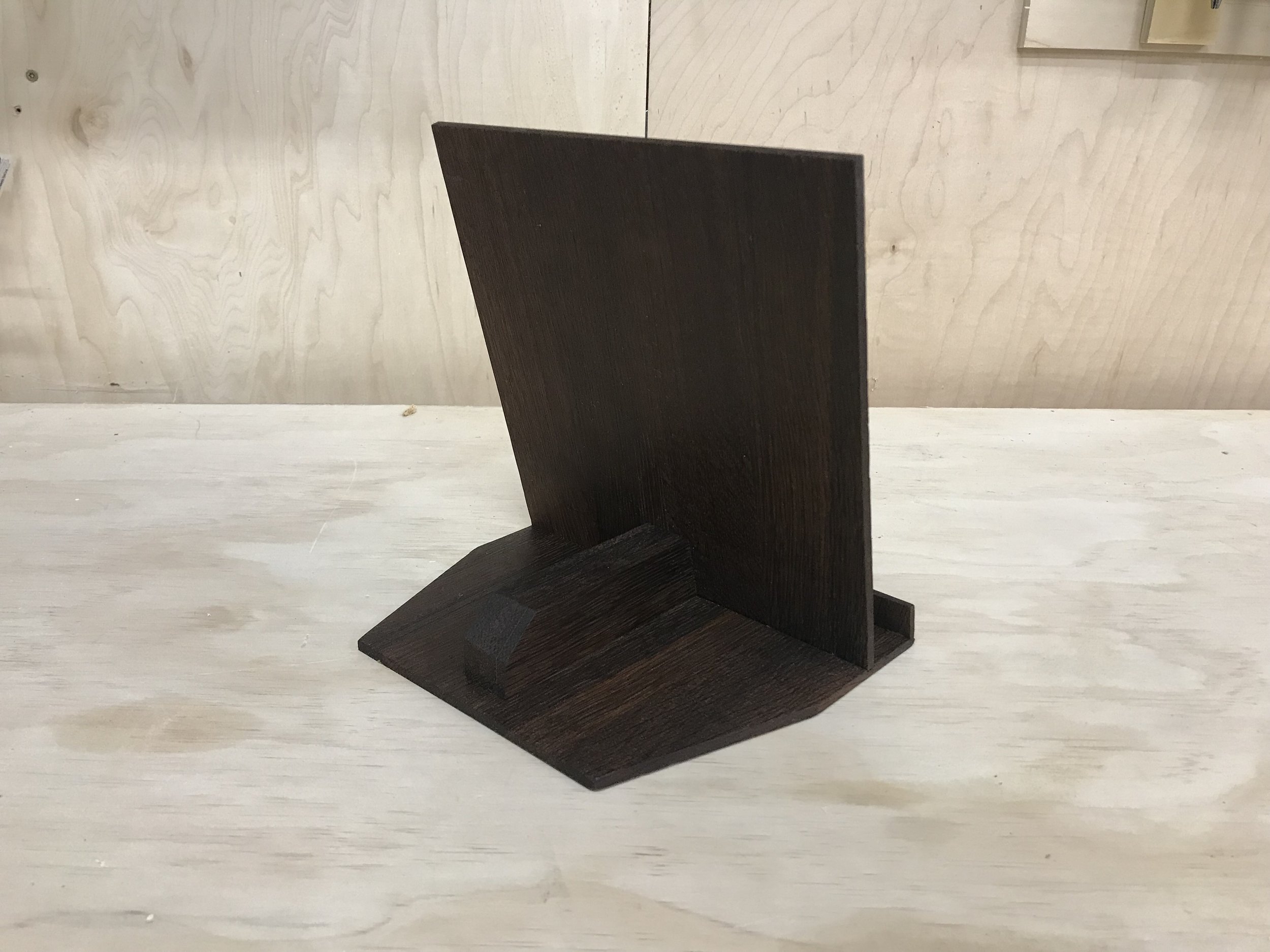
Pic 1 shows how it will all go together. The components are:

  • A base with dados cut in the front and back at 15°
  • A front piece about one inch tall to form a lip (this would go in the front dado)
  • A back piece about 9" tall that would serve as the actual stand (this would go in the middle dado)
  • A support piece in the back (previous step) to serve as structural support to the back piece

I began by gluing up the support piece (Pic 2), using a scrap piece to line it up properly with the middle dado (Pic 3), and then checking to make sure it is square (Pic 4). I then clamped it in place for about 30 minutes to cure (Pic 5).

Next I could add in the back piece (Pic 6), which was a little tricky to clamp but I found having the back support piece in place and then clamping both sides down to my work surface worked best (Pic 7).

Lastly, I glued in the front piece. This was a bit trickier - I ended up using a little excess block to clamp the front piece too (Pic 8) with a squeeze clamp, and then gently applying other clamps all around it - just enough pressure to not break it or mess things up (Pic 9).

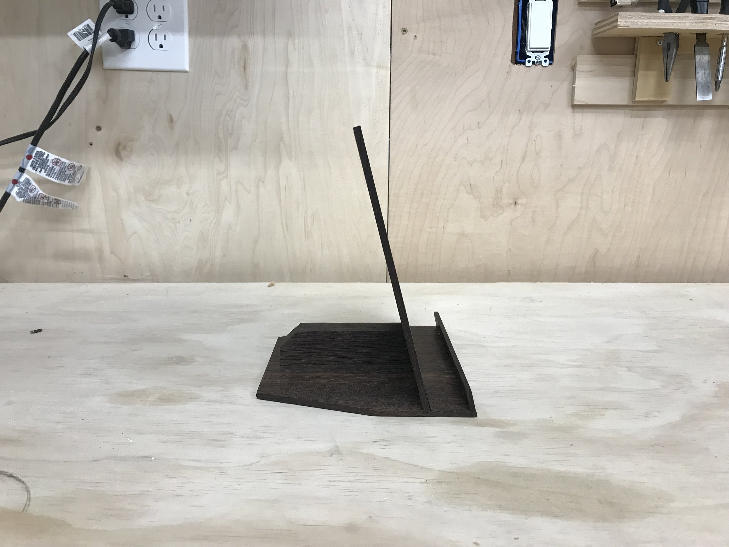
Pic 1 shows how everything came together. I thought it was a bit "block" after seeing it in this form.

In Pic 2, I tested it out and realized my front piece was about 1/2" too tall and it was blocking the bottom of the screen - no point in having a custom Kindle Fire stand that doesn't fit!

I went over to my disc sander and sanded down that front piece, as well as clean up all of the edges to be square and smooth (Pics 3-4).

I wanted to remove some of the blockiness of the piece, so measured out and marked an arbitrary angle to give it more shape (Pic 5). I then used my miter gauge set at that angle to make a pass on each side of the piece to cut those angles safely (Pic 6). Lastly, I added a bevel to the back support piece (Pic 7). Again, no set measurement - just trying to give this thing some angles.

I used some 320 grit paper in Pics 1-2 to sand down all of the edges and surfaces to their final form. Off camera, I cleaned off the piece with some compressed air. These photos show the results of adding the angled cuts on the back as well as the rear bevel.

Last up, I added some food safe mineral oil to bring out the color and grain - and it was beautiful and finished (Pics 3-4)!

And then the tablet stand was done. This wood is beautiful and it has such a unique smell to it and the functionality of it in the kitchen will have a daily benefit to us moving forward. It's super fun to take something old and turn it into something you'll use everyday!

As always, thank you for reading! I would be so grateful if you could please subscribe to my Youtube Channel for future projects.

I put out videos every few weeks.

Cheers! 
Zach


Building my Kitchen Island


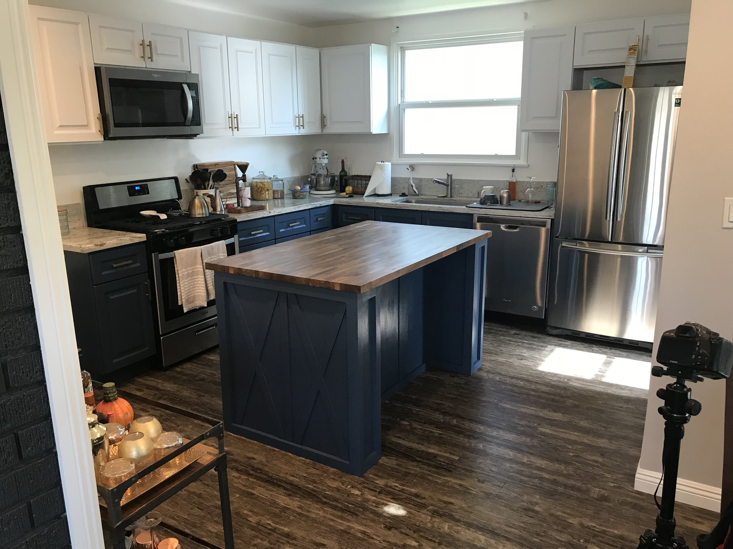
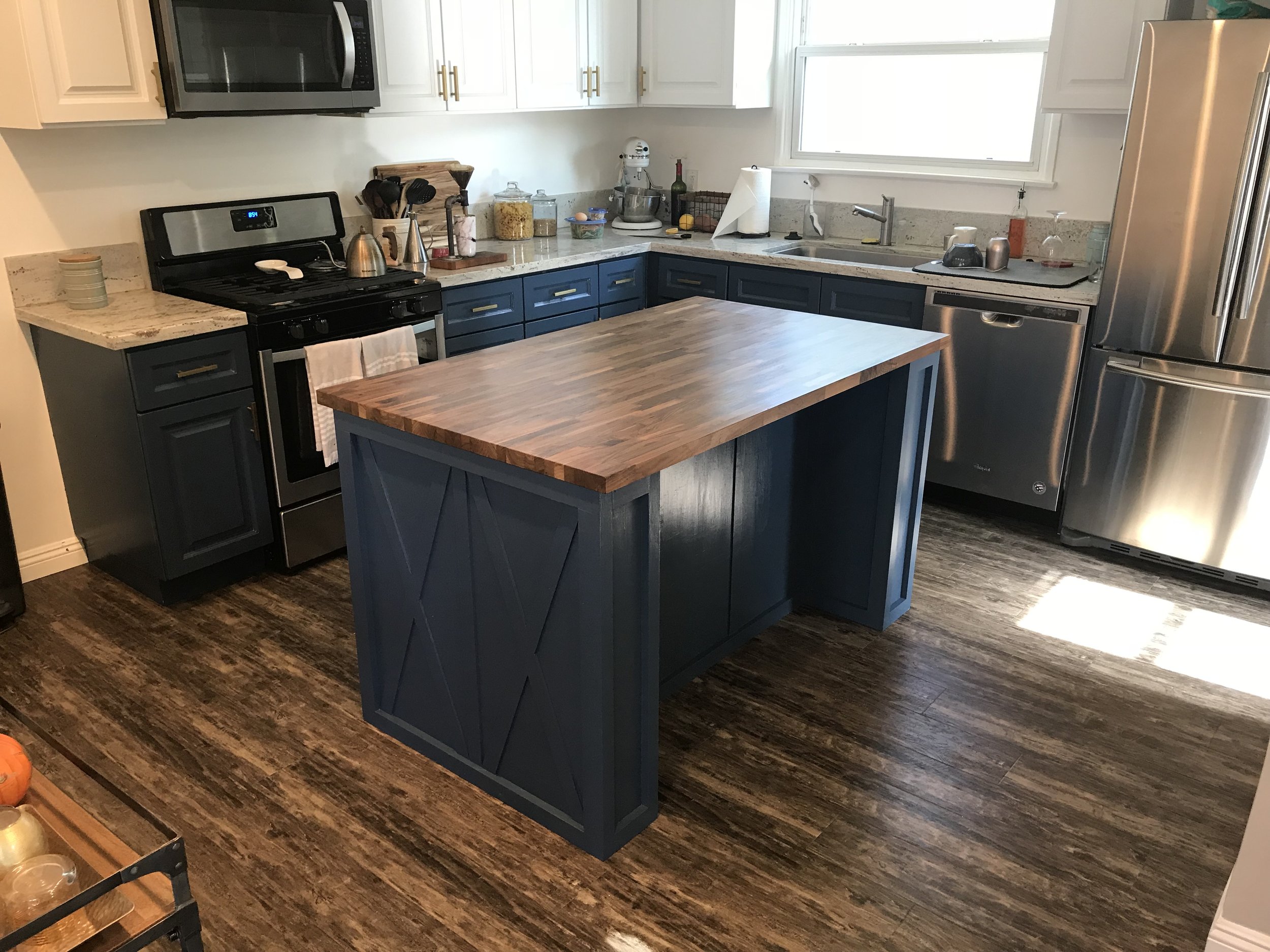
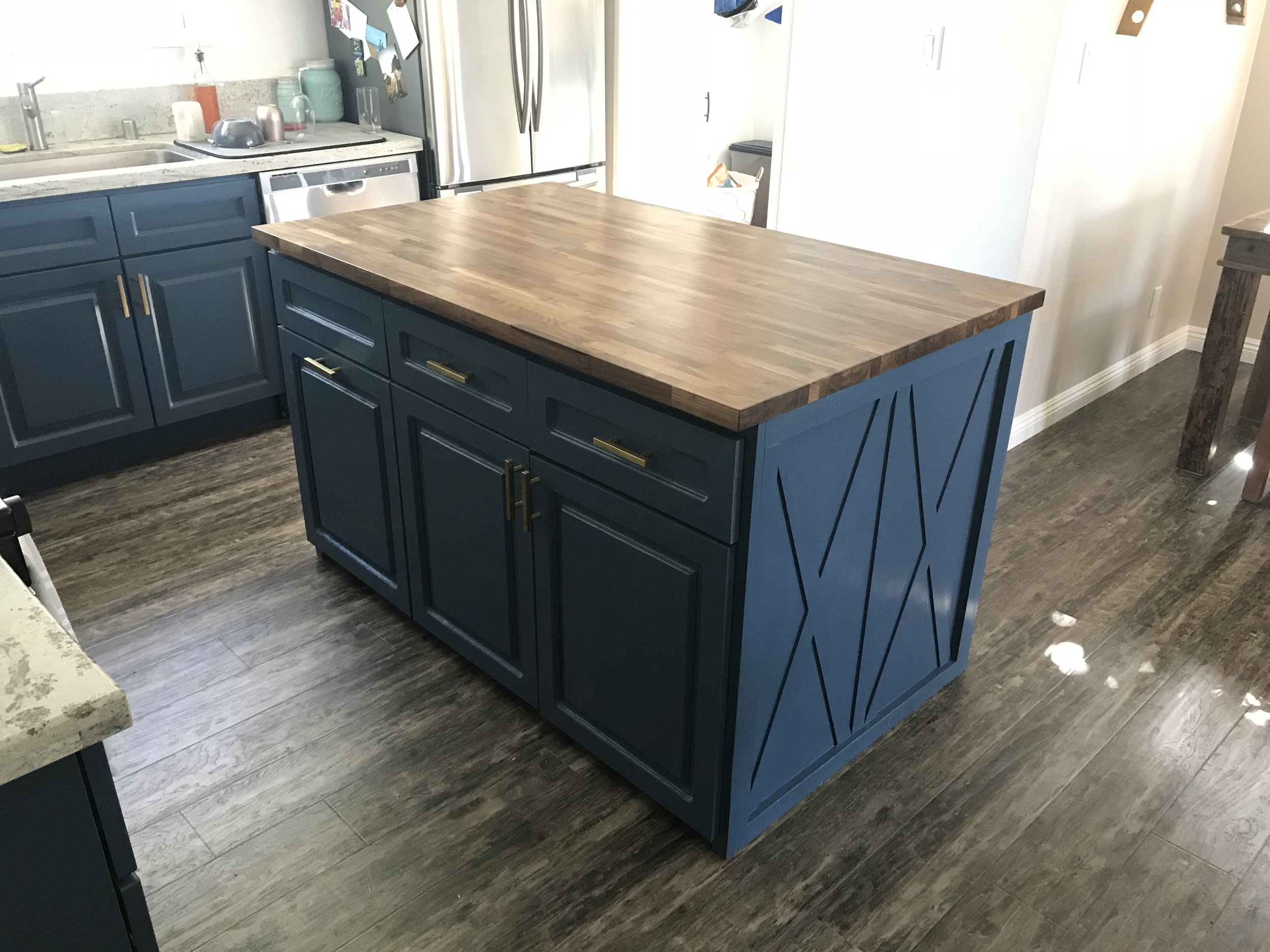
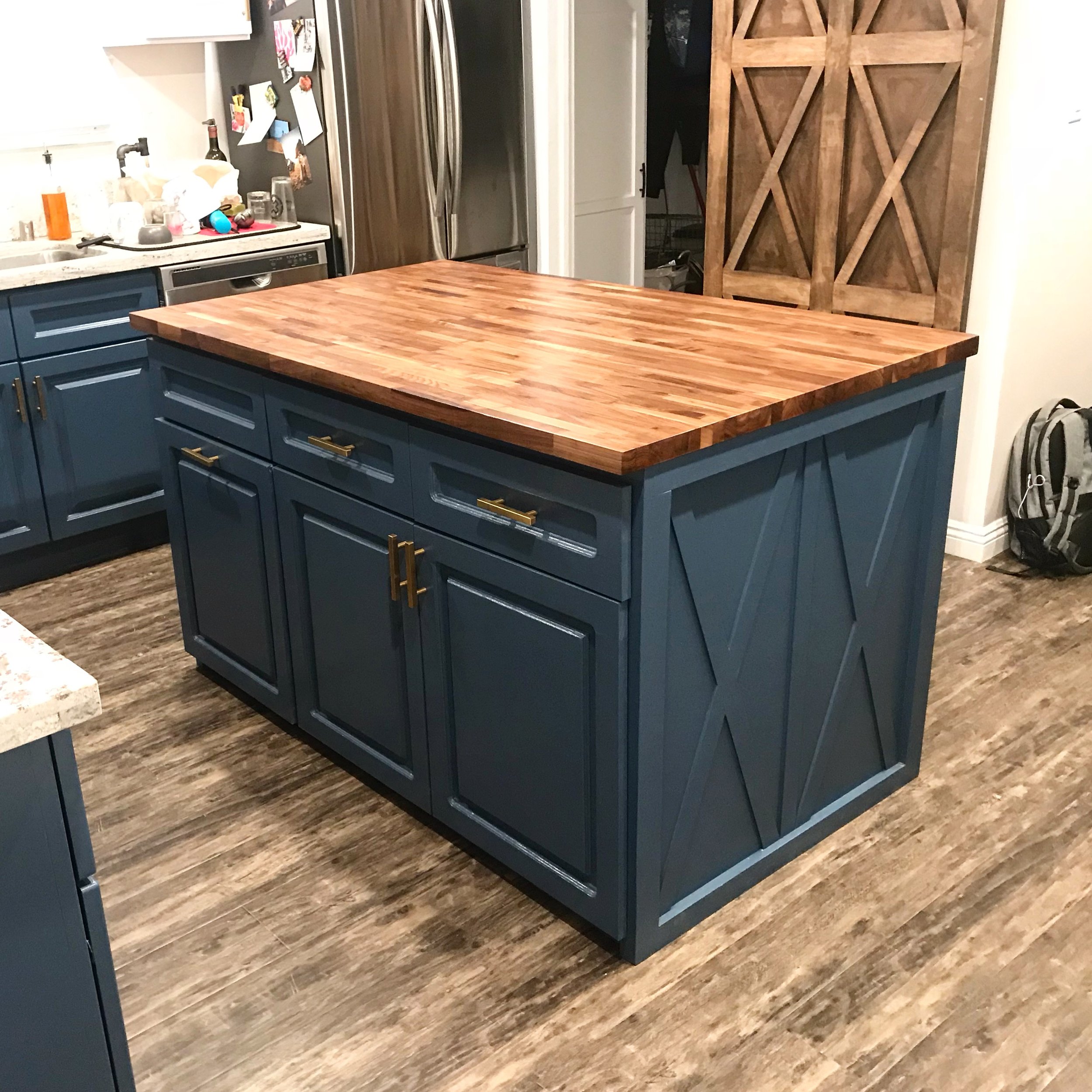
I was quoted ~$3,000 for a custom kitchen island with a butcher block top. No thanks...I'll just make my own for around $850 :-)

This was above and beyond the most ambitious project I've ever tackled. I'm grateful to have done it, so proud of the final result, and happy to share my process. Full video is below, followed by all the tools and materials I used, plus full steps in the article.

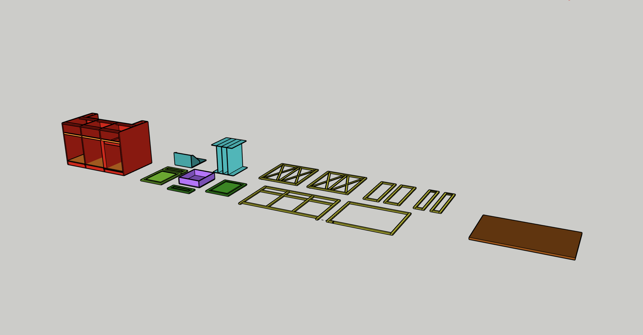
After a year, I finally learned SketchUp enough to properly design all of the components of this. Here is the file for download.

MATERIALS

  • 2 x 3/4" Full Sheets of Purebond Plywood

  • 2 x 1/4" x 4' x 4' Plywood

  • 1 x 1/2" x 2' x 4' Plywood

  • 24 BF of Poplar (Framing)

  • 3' x 5' Butcher Block (Purchased Separately from Perfect Plank)

  • Primer + Interior Paint

  • Wood Filler + Sand Paper (80-320 grits)

  • TiteBond II Wood Glue: http://amzn.to/2peRFus

  • The Good Stuff for Butcher Blocks: https://amzn.to/2OsLlLp

  • ~200 x 1 1/4" Pocket Hole Screws

  • Cabinet hardware (recycled), drawer slides (from Home Depot), and drawer pulls (from Amazon)

TOOLS

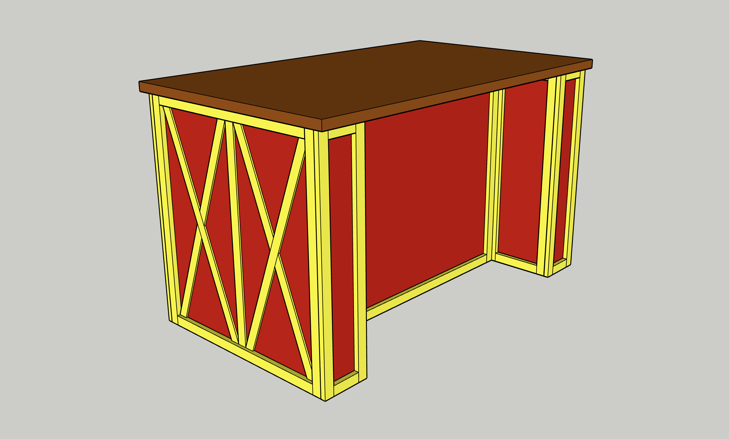
Below are a few stills of the SketchUp design of the entire, as well as a layout of all the components of the build.

Time to get to work!

The main structure of this was built with 3/4" plywood - 2 sheets to be exact. Pics 1-3show me breaking it down into the various components for my build. The design of my island would have three drawers and cabinets on one side, and a 12" recessed area on the other side for two stools, and would measure 3' x 5'. Pic 4 shows my final cuts for the structure.

Everything on this project in terms of structure is held together with pocket holes. I think I drilled an used around 200 1 1/4" pocket hole screws for this build. I use pocket holes for nearly every project I work on, and highly recommend the tool!

Pics 1-4 show me drilling, gluing, setting in place, and using my impact driver to assemble. I was careful to keep everything as square as possible in this step - this really wasn't the project to rush through! Pic 5 shows one of the two legs that would help form the recess for the two stools - I used a scrap block to help keep the spacing even and not "cup inward". Pic 6 shows me cutting horizontal stretchers (all at once to keep even) that would go across the top and bottom to properly space out each side and add structural support.

Pics 7-9 show me using more glue and screws to assemble final pieces of the framing. This wasn't hard - it just took a while and some careful measuring to get everything precise and in it's place!

After getting the framing together, I divided the piece into three even quadrants (Pic 1) and ripped additional 3/4" in plywood on the table saw (pic 2). Pic 3 shows those two pieces in place after I used glue and screws to evenly attached. I'm also attaching a few horizontal stretchers in the same piece that will serve as dividers between the cabinets and the drawers.

Pics 4-6 show me using small strips of 3/4" plywood and pocket holes to glue and screw in place at the base so that bottom shelves could be attached on top.

The next step was super easy - I took 1/4" plywood and ripped it to length and width on the table saw (Pics 1-2) and then attached into place - the relative sizes of each piece of plywood are based on the relative size of your bottom shelves - I think mine were around 18" x 20" each. Then, I attached everything using brad nails (Pic 3).

My fiancé wanted one of the cabinets to store really large cooking sheets - something that just isn't readily available in most kitchens. Part me also thought it could store a custom cutting board I build down the road, so I was all for it. To make these, I broke down more 1/4" plywood on the table saw into two sets of wood (Pic 1).

The first set would serve as base and roof dividers (Pic 2), while the second set would serve as the actual dividers (not shown, but featured in Pics 6-7). I applied glue and then started laying them in place (Pics 3-4). I did so by using another scrap piece to properly space them. I then used brad nails to tack things in place (Pic 5).

You can see how using a spacer in this way allowed me to go back after floor and ceiling dividers were attached so I could slide in my larger pieces (Pic 6). These were held in place in their final form (Pic 7) using just glue. This method allowed me to do this quick and efficiently without worrying about cutting even rabbits in the thin plywood, and it was cleaner in design (at least in my opinion!)

Look - drawers are super boring, so I'll spare you. In Pic 1, I used left over 3/4" plywood from the structure to rip two sets of drawers that were about 4.5" tall. Then, in Pic 2, I lowered my table saw blade and made two separate passes to cut rabbits that would hold the bottom shelf later on. To elaborate - my blade is 1/8" thick, so I made one pass with the blade 3/8" high (half the thickness of the plywood), then moved the fence over 1/8" inch and made another pass, giving me a 1/4" rabbit to insert the bottom drawer shelf later on.

I then drilled and used pocket holes to assemble the shelf (Pic 3). After cutting my bottom shelf (1/4" plywood) to length, I inserted it into the rabbited joints (Pic 4), then attached the fourth side of the drawer (Pic 5) and closed it off with pocket holes.

Last up, I added drawer slides to each side, using a spacer block that I cut to keep things parallel and even on each side (Pics 6-7). I hated this part, but it was necessary (obviously!). Pics 8-9 show me installing the subsequent drawer mounts (also not fun, but necessary!).

Most cabinet furniture have what are called "face frames", which are really just nicer hardwoods used to give your cabinets a face frame and cover up the layers of plywood. I always planned on painting my island, so using four-quarter poplar was perfect for my needs. I started by ripping all of my material into 1 1/4" strips (Pic 1), and then cut all of my pieces to length on the miter saw (Pic 2). This was entirely relative to my own island, so no need to bore with measurements, but be assured that I took my sweet time measuring out exactly how much material I'd need, the exact lengths I'd need, and how it would all come together.

Pic 3 shows me laying it out to make sure I had everything for the front side of the island (the side with the cabinets). Pic 4 shows me using pocket holes to begin assembly, with Pic 5 showing me using glue and pocket hole screws to assemble the pieces. These screws were all on the backside of the material, so they'd be totally hidden. Much YouTube research would tell me that this is a very common way to assemble face frames. Having a big flat even surface to work on and clamp things down was imperative (Pic 5 again).

Pic 6 shows me checking to make sure things were even. This step was so important for the build - basically, if you start with one side that is basically perfect, you can then do all subsequent sides one after another and things should remain perfect and fall into place properly as you can do them one at a time.

Pics 7-9 show me using glue and brad nails to hold everything in place.

NOTE - I would not recommend using brad nails to tack things in place unless you plan on painting your island as you'll see them and it will look bad. Since I planned to paint this, I knew I could use wood filler to fill in all holes and cover up later.

As I said before, once I had my front faces in place, each piece after was relatively easy as I could use my front side as a reference point and work my way around the island. By doing things one at a time, each side fell into place and things actually somehow ended up pretty damn perfect.

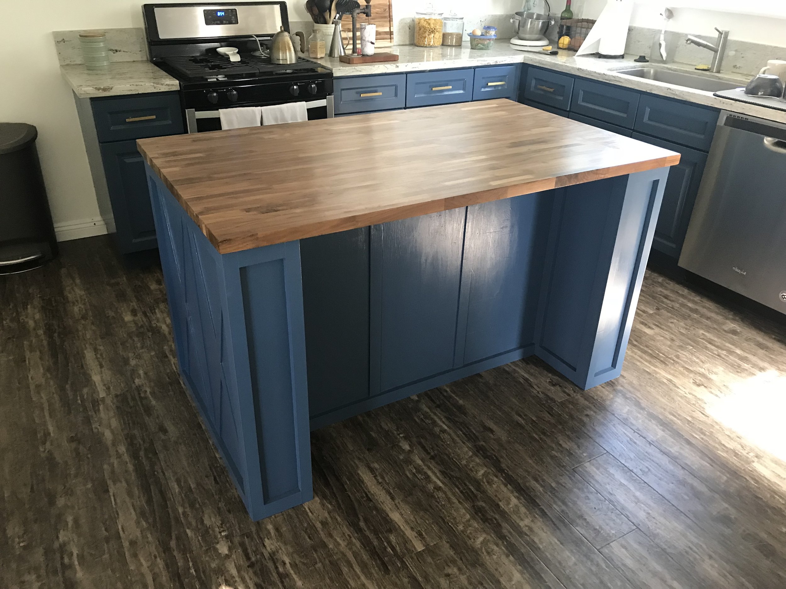
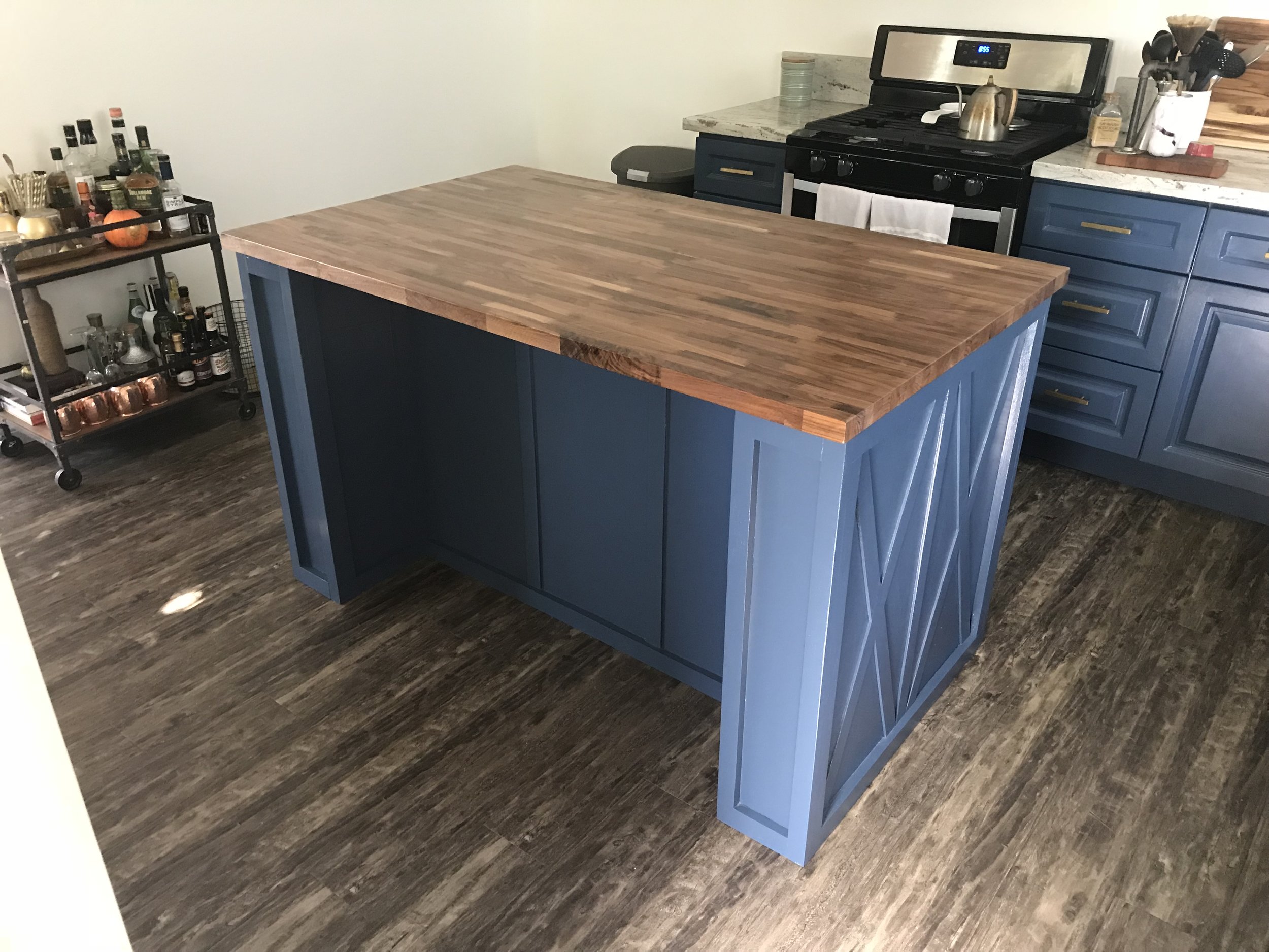
Pics 1-2 show me doing the backside of the island (the recessed area), using clamps, glue, and then brad nails to get things perfect.

I then went back with food filler in Pic 3 to fill in around 80 brad nail holes, followed by sanding with 120 grit sand paper against a wooden block to flatten everything (Pic 4). The result of this was perfect.

Pic 5 shows something that actually kind of looks like an island!

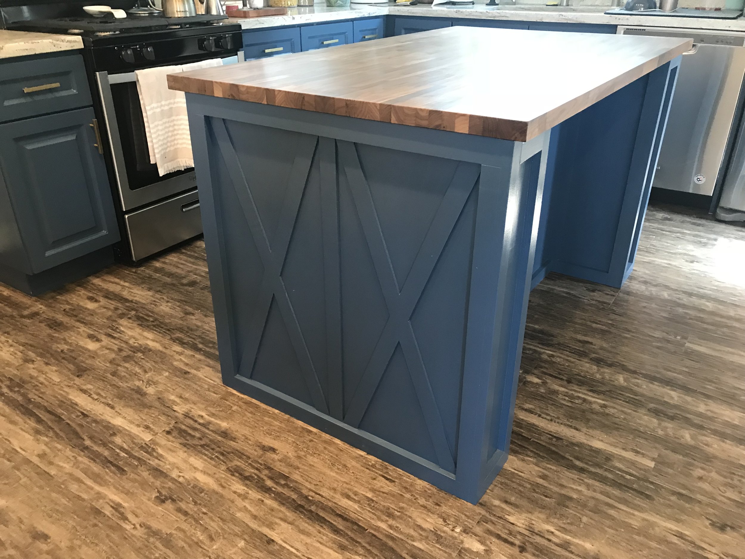
Beyond the hardwood face framing I just walked you through, we wanted our island to have additional accents to it - mainly - in the form of pronounced "x's" that stuck out past the plywood but not as far as the hardwood framing.

To make this, I cut up the rest of my 1/4" plywood on the miter saw and table saw (Pics 1-2) to about 1" wide and roughly the lengths I'd need for the build. Then, in Pics 3-5, I could begin tacking in place each piece.

Our design called for a middle divider on each side, with two x's on each side of it. Starting with the middle divider gave me even sides to measure and work from. Pics 6-8 show me then (as best I could), measuring out, cutting on the miter saw, and then using the stationary disc sander to refine the angles needed to fit x's into each side. I then repeated the process of using glue and brad nails to tack things in place in Pics 9-10).

Pic 11 shows the final result of a few hours of careful measuring, cutting, and gluing in place. Pic 12 shows me adding two more vertical pieces on the face of the recessed side - I have no reasoning for this other than I thought it would look cool. It did.

NOTE - I would use thin hardwoods if you are not painting for this step - I only used hardwood plywood because I planned to paint this and thus could cover up any exposed plywood.

67.jpg

Then, I primed (one coat) and painted (two coats + touch ups) the entire island using a fine foam roller and a nice paint brush. The hardest part was getting into all the corners. I need a spray system.

My fiancé and I agreed that if I could match our current kitchen cabinets (not exactly a simple design!) 80% of the way, then we would be good. Buying cabinets, especially bespoke ones, is damn expensive - like $100 per cabinet. I build my entire set for under $100 and they are damn good (for me).

Part one includes me ripping poplar on the table saw (2.25" wide - Pic 1), and then cutting things to length on the miter saw (Pic 2). I bought, ripped, and cut enough material for three cabinets and three drawers. Then, I drilled more pocket holes. For this step, my plan was always to go back after and route a rabbit on the backside of each hardwood frame, so I laid out my pocket holes into places where the router bit wouldn't hit it later on (Pics 3-4).

Pic 5 shows how all six cabinet/drawers looked framing-wise. Then, I assembled everything using glue and pocket holes, using a speed square to keep things square and the clamp to keep things flush (Pic 6).

Pic 1 shows me using a rabbit bit on my plunge router to route a groove on the back of each cabinet (as seen in Pic 2). This would be used to accept a piece of 1/4" plywood to fill in the cabinet face.

Pic 3 shows me using a special router bit on the front side of the cabinet frame to give it a nice curved profile. This was close to what my cabinets looked like - but not exactly - I simply don't have the tools to make it look perfect. Again - compromise. Pic 4 shows that as a final result.

Pics 5-6 show me using fine grit sand paper to smooth things down a bit compressed air to clean things off.

Now look - I get it - this is not the "Pro Pro" way to make cabinets. But I'm not a pro - and I don't have pro tools - I have some tools, but not enough, so this method work for me - and it's not for everyone, but I will say that the final result is quite good for the mid-level DIYer (and at about 1/6th of the cost!)

To fill in the space between the hardwood frames, I cut 1/4" plywood down on the table saw (Pic 1). These filler pieces would go on the backside of the frames in the rabbits I cut in the previous step.

Because the rabbiting bit left curved corners, I needed to round over the edges on the stationary sander (Pic 2).Then, using glue and squeeze clamps, I could glue everything in place (Pics 3-5) and let cure for 3-4 hours.

The current drawers in my kitchen are made up of just a hardwood frame and a middle piece - there is no added profile in the middle that is elevated. However, the cabinets have a hardwood frame, a 1/4" backing, and then a middle profile. So I needed to make that for the three bottom cabinets.

I ripped 1/2" plywood down on my table saw (Pic 1) - this was relative to my cabinet sizes - I think they ended up being 1.25" smaller on all four sides than the boarder of my hardwood frames. I then used a router bit from Ryobi to give the pieces a fancier profile (Pic 2) - again - 80% the same to what we currently had. If I didn't tell you they were different, you'd probably never notice...

Pics 3-4 show the final profile, me laying it out and measuring properly for evenness, then using glue and something heavy to glue them down - no finish nails for this step.

Again - I know this is untraditional - but it isn't wrong and I know many others have done things like this before and gotten great results (spoiler - I got great results!). Then I primed and painted everything (1 x primer, 2 x paint + touch ups - Pic 5)

Look, I can make things, and I probably could have made this butcher block top. But there is a risk/rewards thing, and I don't have too much pride to risk hundreds of dollars on nice hardwood only to mess it up later on. Could I have made this myself - yea, probably. Did I want to? Kind of. Do I regret buying it. Hell no.

All in all, I paid about $850 total for this island - $550 being this walnut butcher block. The block was bought from a website called Perfect Plank, and I realized that buying and having this shipped would have cost about the same amount to buy the raw materials. So yea, worth it.

The block comes sanded to 120 on one side (Pic 1), so step one of this (Pic 2) was to sand up to 300 grit as well as break the sharp edges. Then, after cleaning off all sawdust with compressed air (not picture), in Pics 3-6, I used Emmet's The Good Stuff butcher block finisher to finish it. You rub in the goop in a circular fashion, working it into the wood, then come back after 15 minutes and wipe off excess using a straight motion that runs with the grain.

Few tips I got for this. First, finish all 6 sides of the block at once as to avoid uneven exposure to elements which could cause cupping and/or warp. Two, don't spray water on the unfinished wood to raise the grain - that can also lead to warping over such a large surface. I headed their advice and did everything they recommended and it came out freaking perfect (Pic 7). I did go back after 12 hours, sand down with 400 grit lightly, clean off with a damp rag, and then apply one more coat of the finish in the same fashion as before (not pictured).

This wasn't very fun and I dreaded it.Pic 1 shows me installing the trashcan slide from the backside. I made this little base out of scrap plywood and attached using 1 1/4" inch pocket hole screws, and then attached drawer slides to the boarder.

Pic 2 shows drilling a recess in the back sides of the other two cabinets that would accept hinges. This was nerve racking, but worked out in the end. I then pre-drilled, screwed in, and attached the cabinets to the hardwood framing (Pics 3-5).

Few tips here:

  • Buy new hinges - I used old ones from a kitchen remodel and although they worked, newer hinges allow you to install and adjust things on a micro level to get even. With mine, I had no wiggle room, so I had to be extra precise.

  • Take your damn time! I spent about 5 hours doing this (on and off) measuring, marking, drilling, checking again, attaching, and just generally getting everything lined up so it was perfect. This has to be perfect, and I had come so far in this build, I wasn't about to waste my efforts

Pic 6 shows me putting in the trash can drawer.

Last up was to install the drawer faces. I carefully mesaured out the centers of each drawer using a drywall square and speed square, and then used a punch to mark the locations for holes (Pic 1). It also helped having one set of hardware on hand to confirm your measurements were accurate.

Once I did, I pre-drilled holes to accept screws (Pic 2). To hold drawers in place, I used hot glue and pressed the drawer face up against the drawer itself, using a spacer to keep things even (Pics 3-4). I then could use the same pre drilled holes to drill through the drawer faces and through the drawer (Pic 5).

Finally, I could attach drawer handles from the reverse side using the hardware included in the kit (Pic 6). I repeated this process for the cabinets below and the trashcan in Pic 7 (easy peasey!).

I built my island knowing I could physically move it to its final home. If you don't have a way to move something that is 3 feet wide (Like having double french doors in your backyard - Pic 2), then make sure you account for what you can actually fit!.

My dad and I took the long journey from my garage / shop, around the house, to the back, and into the kitchen (Pics 1-3), and then sat it in its final place. This thing is so dang heavy, I have not and do not plan to actually mount it to the floor.

In Pics 4-5, we then moved the butcher block to it's final place. This thing made it even heavier - at this point I could lean and push my whole body against it and it didn't move a millimeter.

By the way - seeing this beauty in it's near final state in our kitchen was amazing.

Last step! Last step!

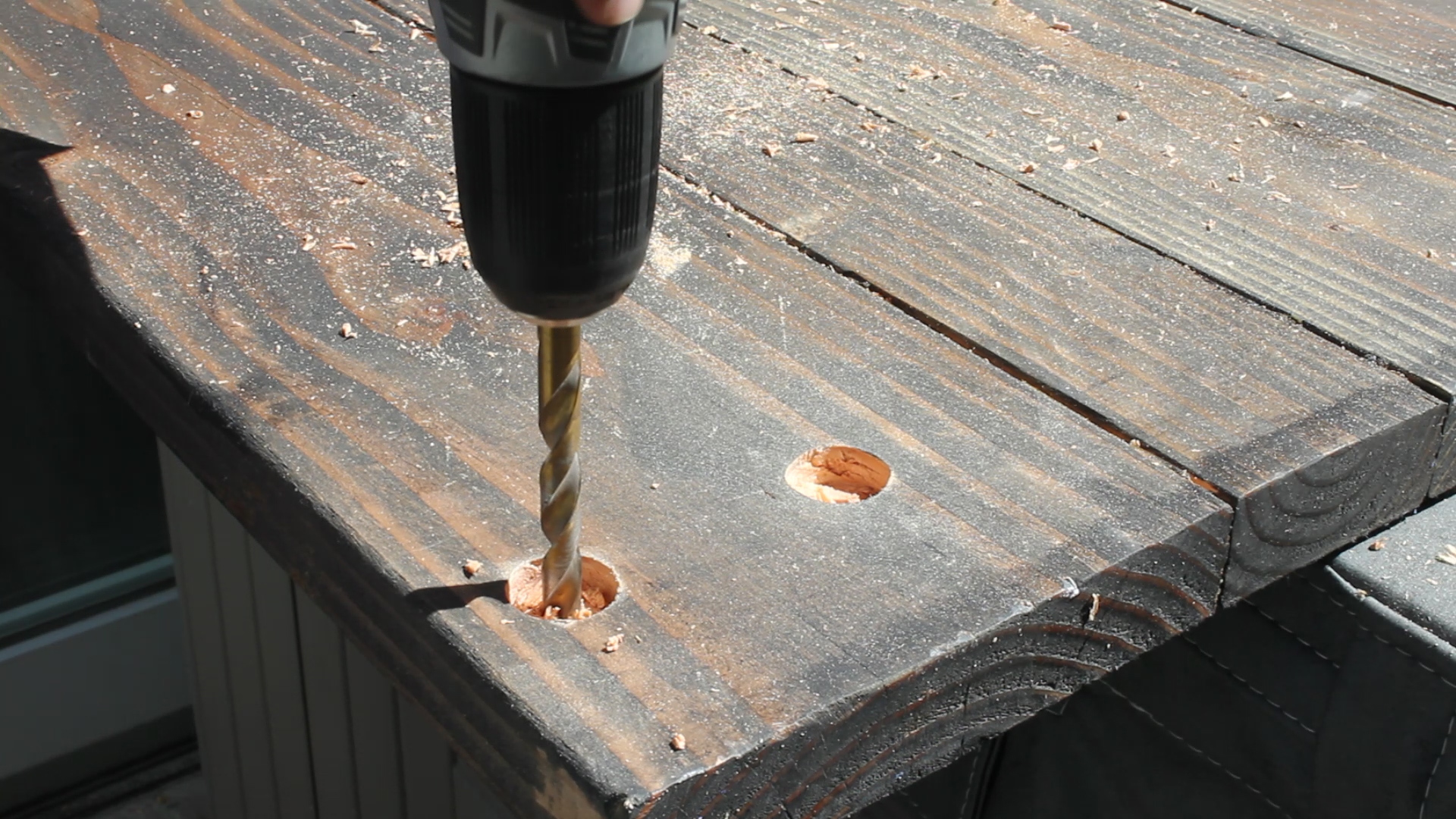
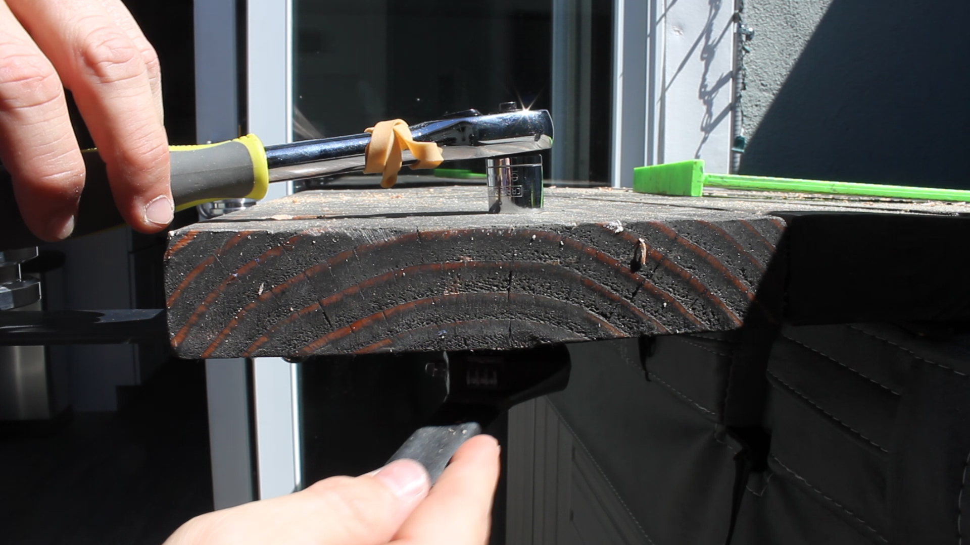
To attach the butcher block to the island, before moving into the kitchen, I drilled four holes in each corner top support piece that was 1/2" wide (Pic 1). To actually attach base to block, I'd am using a washer and pocket hole screw (Pic 2). Drilling a hole larger than the screw and using a washer allows for expansion and contraction as the weather changes throughout the year (advice from my father in law).

Pic 3 shows my fiancé and I marking and measuring the final location of the block.

Pics 4-5 show me using my impact driver to drive in the final screws.

AND THEN WE WERE DONE BABY!

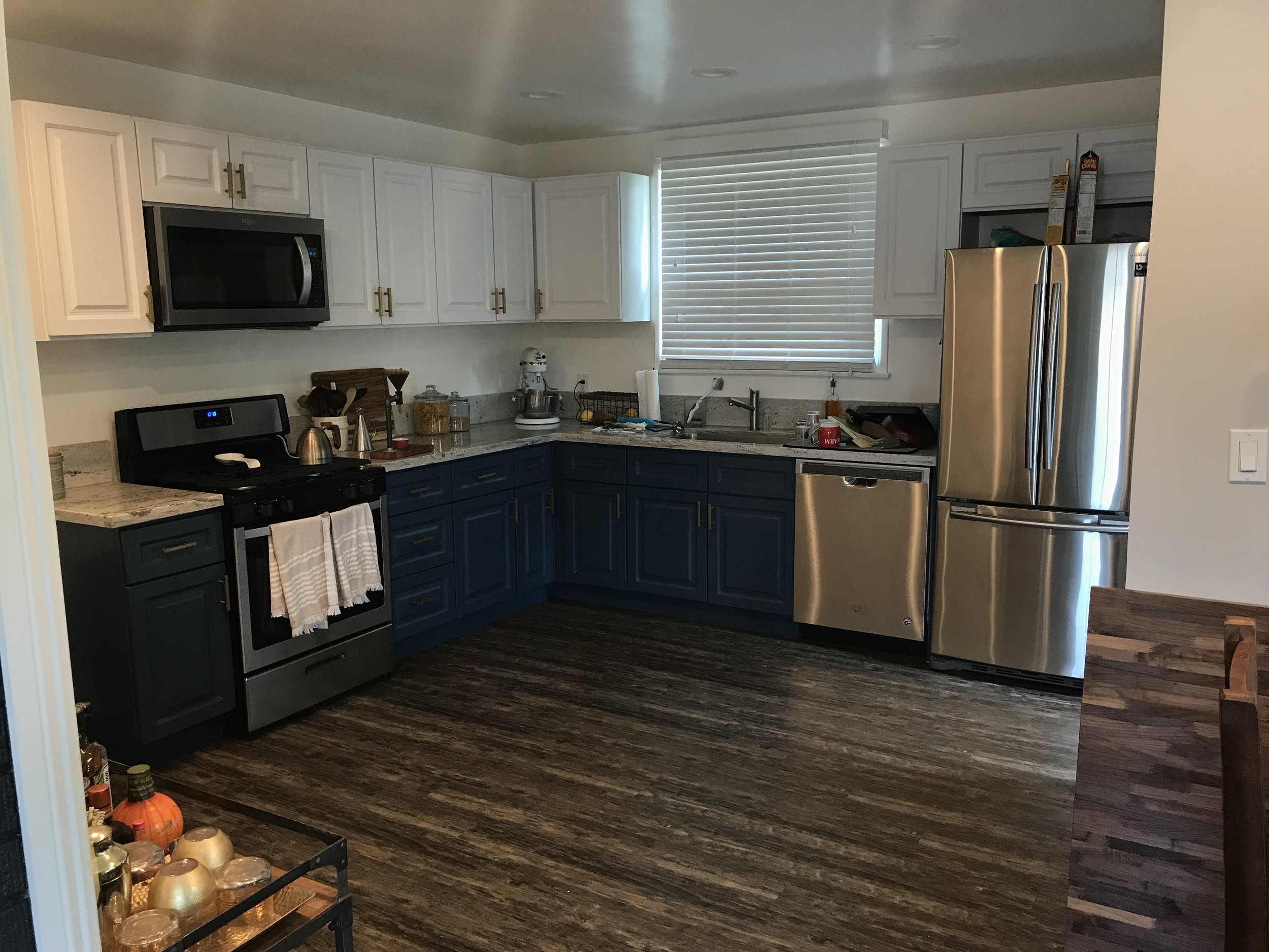
I could not be more excited about this thing. It is just awesome and I'm going to go ahead and pat myself on the back for building something I never knew was possible (in my own skill set). I encourage you to get out there and tackle things outside your comfort zone - cause damn is the payoff amazing. Take a look at the final pics, as well as the last two which show a before/after of our kitchen space (why was there no island there to start?!?).

As always, thank you for reading! I would be so grateful if you could please subscribe to my Youtube Channel for future projects.

I put out videos every few weeks.

Cheers! 
Zach
 

Making a Huge Assembly / Out feed Table


I made my first big purchase for the shop - a SawStop. Safety has become paramount for me as a hobbyist maker, so in addition to the purchase, I knew it was time to build a big assembly out feed table! Below is the full video build where I talk about why I built my table the way I did and how I went about it. Materials and tools are below as well! Hope you Enjoy!

MATERIALS
3 x 3/4" x 4' x 8' Sanded Plywood
~100 x 1.25” Pocket Hole Screws: http://amzn.to/2p5vKYw
1” Brad Nails: http://amzn.to/2oNLc8W
TiteBond II Wood Glue: http://amzn.to/2peRFus

TOOLS
SAWSTOP Contractors 30” Saw: https://amzn.to/2Luh91q
Circular Saw: http://amzn.to/2q1l5wn
Power Drill: http://amzn.to/2q1l5wn
Cordless Brad Nailer: http://amzn.to/2p1dYFD
Impact Driver: http://amzn.to/2q1l5wn
Miter Saw: http://amzn.to/2q1klHw
Miter Saw Stand: http://amzn.to/2p1072e
Plunge Router: http://amzn.to/2p15eiC
1” Dado Bit: http://amzn.to/2eR6tOO
KREG K5 Pocket Hole Jig: http://amzn.to/2qb8S7t
Kreg Clamp: http://amzn.to/2riyHU8
12” Speed Square: http://amzn.to/2phZUIt

Above are new renderings completed in SketchUp of the table. You can access those plans for purchase ($4.00 USD) here.

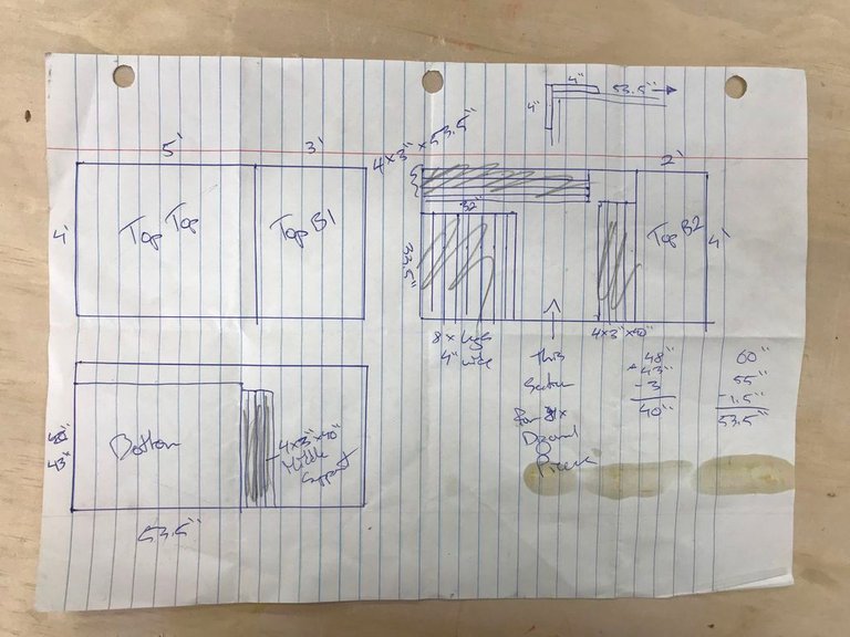
My design called for 3 sheets of plywood. Some were to remain quite large, others would be broken down via a circular saw, table saw, and miter saw. In pics 2-3, I am breaking down the (super detail and awesome hand drawn) cut list featured in Pic 1. I labeled my pieces in Pic 4, and then stacked the bigger pieces off to the side while I broke down the smaller parts.

My legs were composed of two pieces of plywood - one 3" wide, butt jointed against another piece 3.375" wide. I'm ripping them down in Pic 1, and then "gang" cutting them in pic 2 - I believe they were cut to just under 32" which would give me a final height of my table just under 34" (~height of my table saw).

In Pics 3-5, I drilled pocket holes every 8-10 inches or so, apply glue, and then use pocket hole screws to combine the two pieces together. Pic 6 shows all four legs built identically.

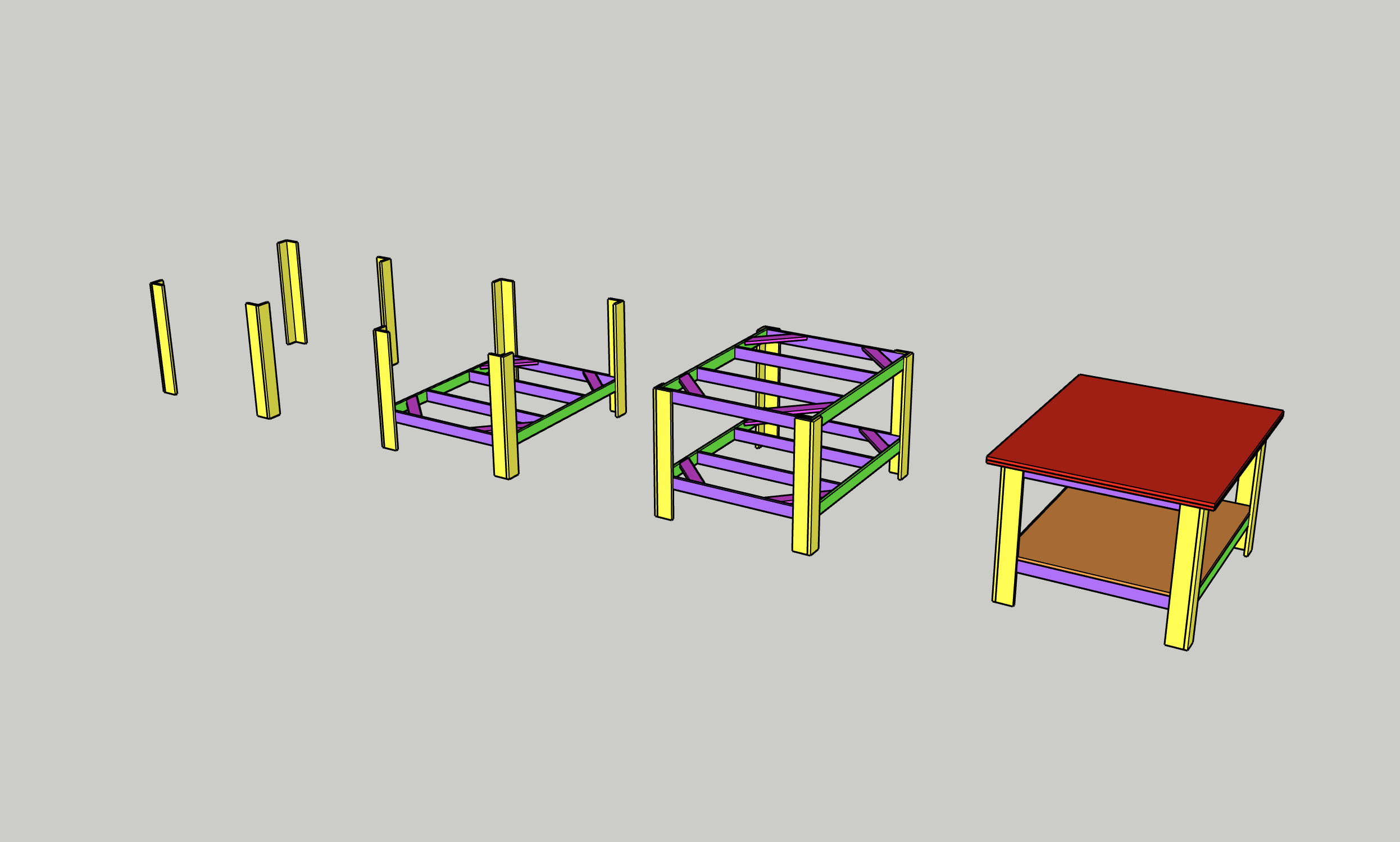
Framing this table to combine legs was relatively straight forward. Each leg was connected by a stretcher running from leg to leg, on the top and bottom, so that I'd have two shelves.

Pics 1-3 show me using glue and pocket hole screws to combine a set of legs together at the top and bottom (then repeating for the other set of legs), resulting in two sets of legs in Pic 4.

I ripped and cut a few additional strips with 45° miters on the end in Pic 5, then used glue and pocket hole screws in Pics 6-7 to attach them at the corners to add sheering strength. Lastly, in Pic 8, I attached 4 x stretchers at the bottom that would eventually bring the two sides together. You'll see what I mean in the next step.

Pics 1-2 show me taking the two sides and combining together again using glue and pocket hole screws with the four stretchers I attached in the previous step. Pic 3 shows the result of this - I added more miters to the corners to fully strengthen the bottom piece. I used glue and finish nails in Pics 3-5 to hold down the shelf - this shelf was cut at the beginning of the build when I was breaking down my big sheets.

Then, in Pics 6-7, I repeated the entire process for the top that I had just done for the bottom, adding horizontal stretchers, as well as miter'd corners for shearing strength.

Next up was to finish the top. From my cut list, you can see that I planned it out so that left over, I'd have a piece that was 4' x 5' (final top), and two pieces that were 2' x 4' and 3' x 4'. The second two pieces were going to serve the purpose of a permanent bottom shelf, with the larger overall piece serving as a top shelf that could take wear and tear and be replaced if needed.

In pics 1-2, I am moving the table into place and moving the two smaller sheets into place. I then clamped one piece down (Pic 3), and removed the other piece to add glue (Pic 4). This way, everything stayed where I needed it. In Pic 5, I put the piece into place, use brad nails to hold it down (Pic 6), and then off camera, repeated that process for the other smaller piece. Then, I had a complete top.

Pic 7 then shows me moving in the single large sheet on top of that and adding finish nails (Pic 8) to keep it in place. Again, this was so I could go back and remove / replace if I ever wanted as well as add weight and strength to the top.

Because this was going to be an out feed table, i wanted to add miters to the side touching the table saw so that I could pass jigs and other miter tracks through the table saw and onto it if needed. I made sure the table saw was square to the table (Pic 1), and then used the miter gauge that the table saw came with to figure out where to cut my dados (not shown).

I used my plunge router to find the right depth (pic 2), and then took 2-3 passes with a 1" dado bit in Pic 3 for each miter slot, resulting in two nicely cut miters in the table top (pic 4).

After finishing the miters, the table was done (for now). I have so many plans in mind for this down the road - additional storage, drawers, hardwood boarders, more hangers to add essentials (you can see things already being hung), adding casters for mobility.

I error'd on the side of simplicity for this build knowing that I would want to use it and see it in my space and then figure out what would be the best ways to build on it as I progress in my hobby.

If you want to know any materials, tools, or have any general questions answered, you can check out the second step or contact me via my website, thecuttingbored.com and I would be happy to do answer them.

As always, thank you for reading! I would be so grateful if you could please subscribe to my Youtube Channel for future projects.

I put out videos every few weeks. 

Cheers!
Zach


Power-Carving the Infinity Gauntlet


THANKS FOR CHECKING OUT THE FULL ARTICLE!
PLEASE SUBSCRIBE TO OUR YOUTUBE CHANNEL BY CLICKING HERE.

My full video of the build is below, followed by detailed instructions with tools, materials, and measurements! 

I'm a huge Avengers fan, and am so amped up for Infinity War. I thought it would be fun to tackle a unique power-carving project, by trying my best to recreate the Infinity Gauntlet.

PureBond-HWPW-BL1.jpg

Thank you to Purebond for helping support this project! Purebond is a no-added formaldehyde product sourced and manufactured in North America and is the highest quality plywood material I have ever worked with.

Check out their website here for more information: http://purebondplywood.com/

You'll see from the video above and the instructions below that this took me two rounds to get correct (and I still could improve on it a lot). Hopefully my first time mistakes (mostly rushing and not referencing my designs) can be avoided if you're looking to get into power carving.

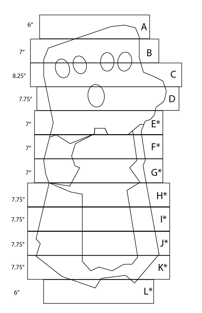
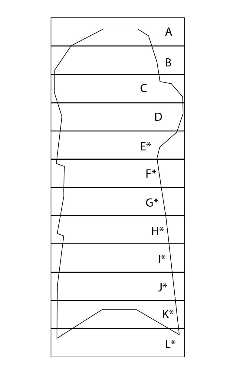
To begin, I found the highest resolution and most "clear" photo I could find of the gauntlet online. I then brought it into Illustrator and sized it to fit in section of blocks that were a little under 1.5" thick (knowing that I wanted to use a 2 x 8 for this project, and that I'd plane it down to something about 1.4" thick). 

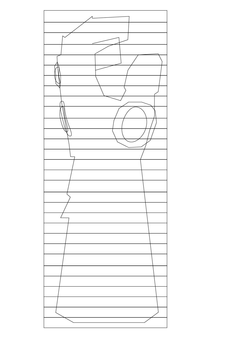
Then, I used the pen tool to trace out the main armor components of the design of it onto the art board. I then took a picture of my own hand from the side, brought that into illustrator, and traced the same profile of it to give me a side profile view of what a fist could look like. 

Had I found any sort of 360 view of the gauntlet, this would have been much easier, but part of the fun of this kind of thing is figuring out ways around not having all the resources you need. 

MATERIALS

Round 1
1 x 2" x 8" x 8' Douglas Fir (from Home Depot)
Titebond II Glue

Round 2
1 x 4' x 4' x 1/2" Spalted Maple Plywood from Purebond
Titebond II Glue
Tung Oil

I designed this project to be built with just one 2 x 8 from home depot - that way, anyone could do it. I used my table saw to rip both sides of it to a little under 6", then planed both sides so that they were very flat for laminating. If you want to skip all this, or don't have access to these tools, you can buy S4S lumber from a local dealer.

Based on the design, I ripped my material into specific lengths on the miter saw (Pics 1-2), and then laid them out on the ground to match my design template (Pics 3-4).

his is not necessary, and I ended up skipping this whole bit the second time around, but if you want to be able to stick your hand in your design, you'll want to cut out holes in the first 9 pieces before gluing up. 

Pic 1 shows me figuring out how many pieces I'd need to cut out a hole in. I used a masking tape ring to make a rough circle in Pic 2. Then, in Pics 3-5, I used a drill and jig saw to cut out holes in each of my pieces, using clamps to hold it steady while I did so. Pic 6 shows me test fitting my hand before gluing. 

hen, using some Titebond II in Pic 1, I applied an even amount of glue to all the surfaces of each piece for lamination. I used my template in Pic 2 to make sure the pieces were lined up, and then clamped it together and let it dry for 24 hours in Pics 3-4. Simple enough. All of these steps could be skipped if you somehow had a big chunk of wood to carve down (like a tree stump, etc.). 

originally planned to use a band saw from my buddy to cut out the outline, hence why I designed the entire thing to be the size it was (so it could fit in the cutting capacity), but it turned out to be too much to handle. So, I used a chain saw instead, which worked much better and was faster anyways. 

fter chainsawing, I switched to my angle grinder and a TurboPlane to power-carve (Pics 1-2). To smooth things out, I used a 40 grit flap disk (Pic 3). These are wonderful, and are an absolute necessity when power-carving. 

This is where I botched things. I thought I knew in my head how I wanted this to look, and I thought I had a great mental image of what the gauntlet looked like. However, I didn't, and by rushing into carving this, the result was something that kind of looked like a glove (Pic 4), but ultimately would never look like the movie version of gauntlet. 

I suppose if you were just trying to create your own take on the glove, then it would be fine, but I wanted mine to be relatively "movie accurate", so I ended up wasting a lot of time trying to fix the problem before just calling it quits and starting over. 

s I said in the previous step, I had pretty much botched the carving job. Rushing, not checking my references, and just thinking that I was on the right path all culminated in something that didn't come out how I was anticipating it. That is the tricky part of these carving projects, especially when you design something in 2D and need to translate that into 3D - you do need some sense of artistic design and spacial understanding because once you remove the material, there ain't no goin' back!

Pics 1-4 show me using dremel tools to add fine details like the the spaces for stones, the finger spacing, and armor details. This took a while, as dremel bits are small and can only do so much at once. 

I went through a sanding phase to smooth everything down in Pic 5, and then finished off with more fine dremel sanding and detailing in Pics 6-7Pic 8 shows a near final result. The stacked wood looked pretty cool, but it just didn't come out how I wanted, and up close, it just didn't quite look like a fist (damnit). 

So, as I have repeatedly said in previous steps, I wasn't happy with how this thing came out. I realized that I had rushed the carving design of it without doing my due diligence to double check the reference photos each time. It was inaccurate, the layers of the gauntlet were all wrong, and it was like trying to put a band-aid on a gunshot wound to make it look more "movie real". Again, that is the challenge of creating something 3D from a 2D design...

I decided it was time for a redesign - and good opportunity for me to figure out what I did wrong the first time around and fix those things as much as possible. Slowing down was the main thing I needed to do...so take that into consideration (and know that with this kind of thing, there is no sure-fire way to make it perfect).

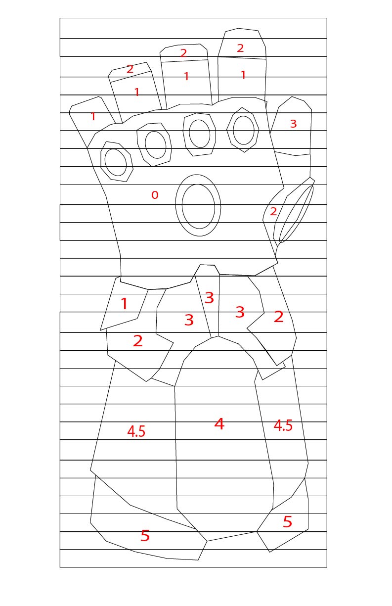
I realized that because I can't 3D model, I'd have to figure out a way to track how deep I was carving. The gauntlet is just a form fitting glove with layers of armor stacked on top of each other, so in order to make them look like layers that slightly overlap, I'd have to come up with a "carve by numbers" system.

Pics 1-2 shows how I designed that. Each main component of the glove layer would have a number associated with it, which would tell me, in terms of layers, how "outside' or "inside" it would need to be.

Having redesigned the the gauntlet in Illustrator to be made from 1/2" plywood that I got from Purebond, I got to work. 

I cut out the squares in Pics 1-2 from a scrap piece of 1/2" spalted maple plywood I had, and then laminated all 30 of the strips together in Pic 3. This actually works better as you don't need a table saw or a planer to get to nice clean cuts for laminating. 

Pics 1-2 show me repeating the same method as before. I glued on my template to the piece of wood, except this time, as I didn't have a chain saw, I power-carved everything. In Pic 2, you see my carving out the hand portion of it - I was VERY methodical and careful about this part, stopping frequently to check that what I was carving looked both like a true hand as well as what my reference photos looked like. Remember, you can't put back material once it is gone. Pic 3 shows the glove after the first round of carving (before detailing) - already 100x better than before!

Pics 4 -5 show me using a forstner bit to separate the thumb and fingers (only way I could think of as I don't have a ball gouge or any other tool to get in those tight spaces, and then a dremel bit to separate the fingers. Pic 6 shows the early stages of carving the preliminary "armor" layer (more on this in the next step).

Now comes the moment of truth (and patience). Remember, armor on anything is just a bunch of individual pieces of metal slightly stacked on top of each other to provide uniform protection, and I really wanted to make sure I achieved this look. 

I was very patient with this step, as I didn't want to repeat my mistakes. I used a sharpie to mark out the design of what I was going to be carving and not carving. Pic 1 shows me marking the first layer of armor. Pics 2-3 then shows me using a flap disk to carve away the middle portion, leaving me with a first layer of armor. I then repeated this process over and over again for the five or so layers I had created, carving away a portion each time, and leaving all previous layers untouched. The result were armored layers that looked like metal stacked on top of each other.

Pics 4-6 show me using a flap disk and dremel drum sander bit to carve out the armor of the fingers (my own design), round over the edges, and add more detail to the main gauntlet armor.This took about three hours, as again, I took it slow, referenced my photos and designs frequently, and in general, took the time to get all the shapes right. I was stoked on the result.

The final steps, like before, were to do everything I could to make the gauntlet as detailed in possible.

This included adding spaces where the stones go (Pics 1-2) using a forstner bit and rounded dremel bit, adding layered detailing around all the stones accurate in Pics 3 and 4 (somewhat) to the movie gauntlet, and then doing a final hand sanding to smooth everything over with some 400 grit paper (not pictured)

This took about 1.5 hours (again, just referencing photos a lot, taking my time, going back and forth to add more detail) - clearly I was a bit obsessed...

The strata look of stacked plywood turned out as cool as I hoped it would. I thought that burning the outside of the wood lightly could add a cool look to it (darken it to look more golden, burn the edges to add definition, and just spice it up). Pics 1-2 show me doing that, and Pic 3 shows how it came out. Not bad, right? Glad I did that!

NOTE - I did this outside, with extreme caution, and very lightly as to not set the entire project on fire!

To finish it, I applied a few coats of tung oil. In hindsight, maybe just doing a few coats of poly would work better (Pics 4-5). It looks great, but the poly would be cheaper, easier, and give a better clear-coat satin look. Pic 6 shows a not great up close photo. 

Above are a bunch of close up grabs of the final piece. Pretty cool, right? Not perfect, but nothing is - I'm happy with it, and it was fun to step outside my comfort zone and learn in the process.

POWER CARVING TOOLS

TOOLS

FILM / EDIT EQUIPMENT

As always, thank you for reading! I would be so grateful if you could please subscribe to my Youtube Channel for future projects.

I put out videos every few weeks.

Cheers! 
Zach


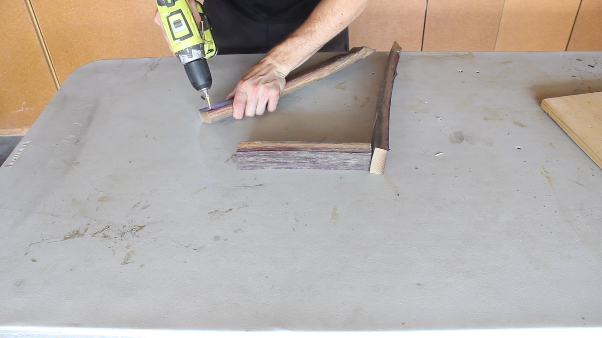
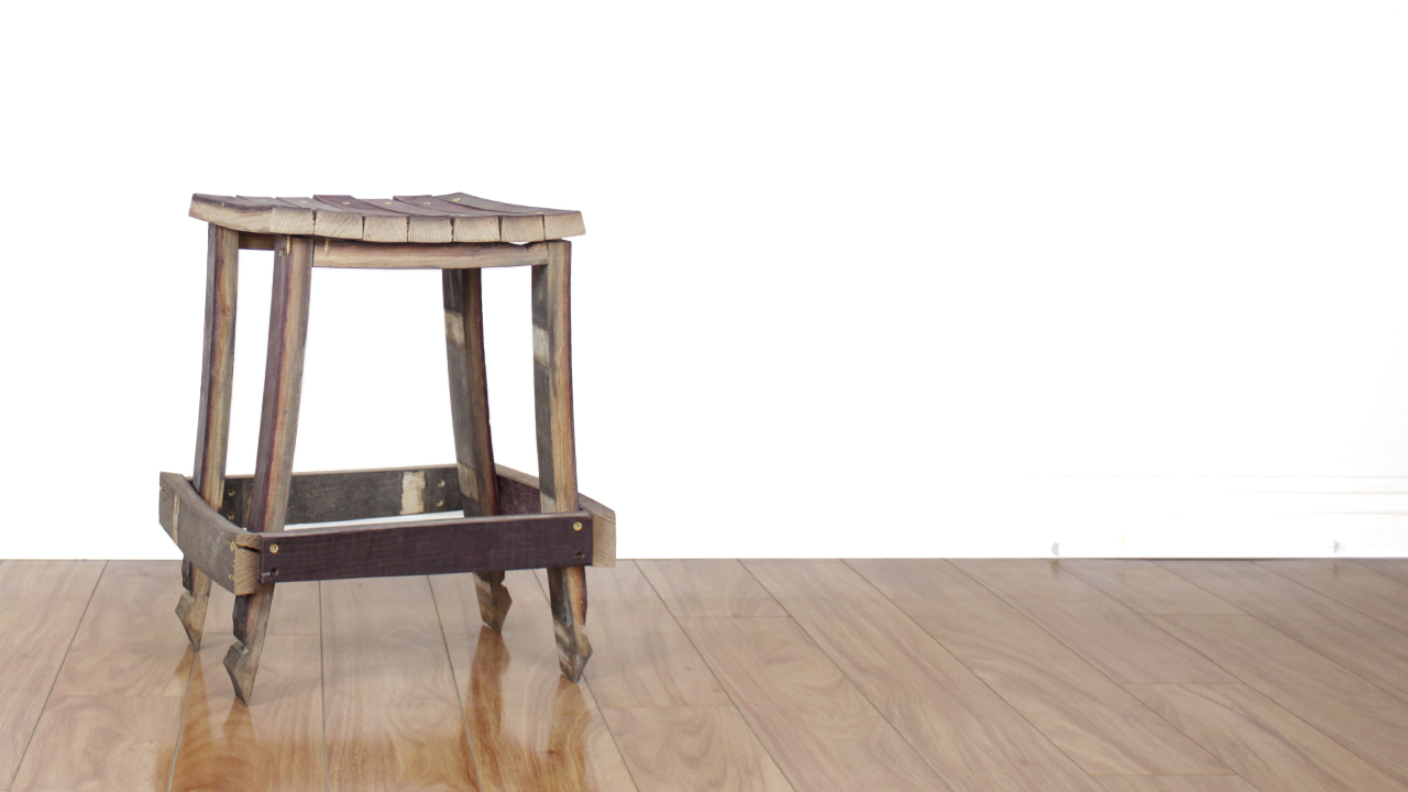
How to make a Wine Barrel Stool


Thanks for checking out the full article!
Please Subscribe to our Youtube Channel by clicking here.

My full video of the build is below, followed by detailed instructions with tools, materials, and measurements! 

MATERIALS
8 x Wine Barrel Staves (Similar width)
~30 x Wood Screws

Image 1.jpg

Above is a picture of the 8 x Oak Wine Barrel Staves I have. They have a ton of character and are so awesome and I was so stoked to make something with them. The thing to note is that, if possible, you should get staves that are of similar width and thickness to make the project easier. 

I had seen a cool / simple design for a barrel stool and I did some math in my head and figured out that I had enough material to make it (this was just based on a picture - no designs or measurements, so I just went with what I thought would work and made my stool the size that made sense with the material I had). So I made my cuts!

Cut Designs.jpg

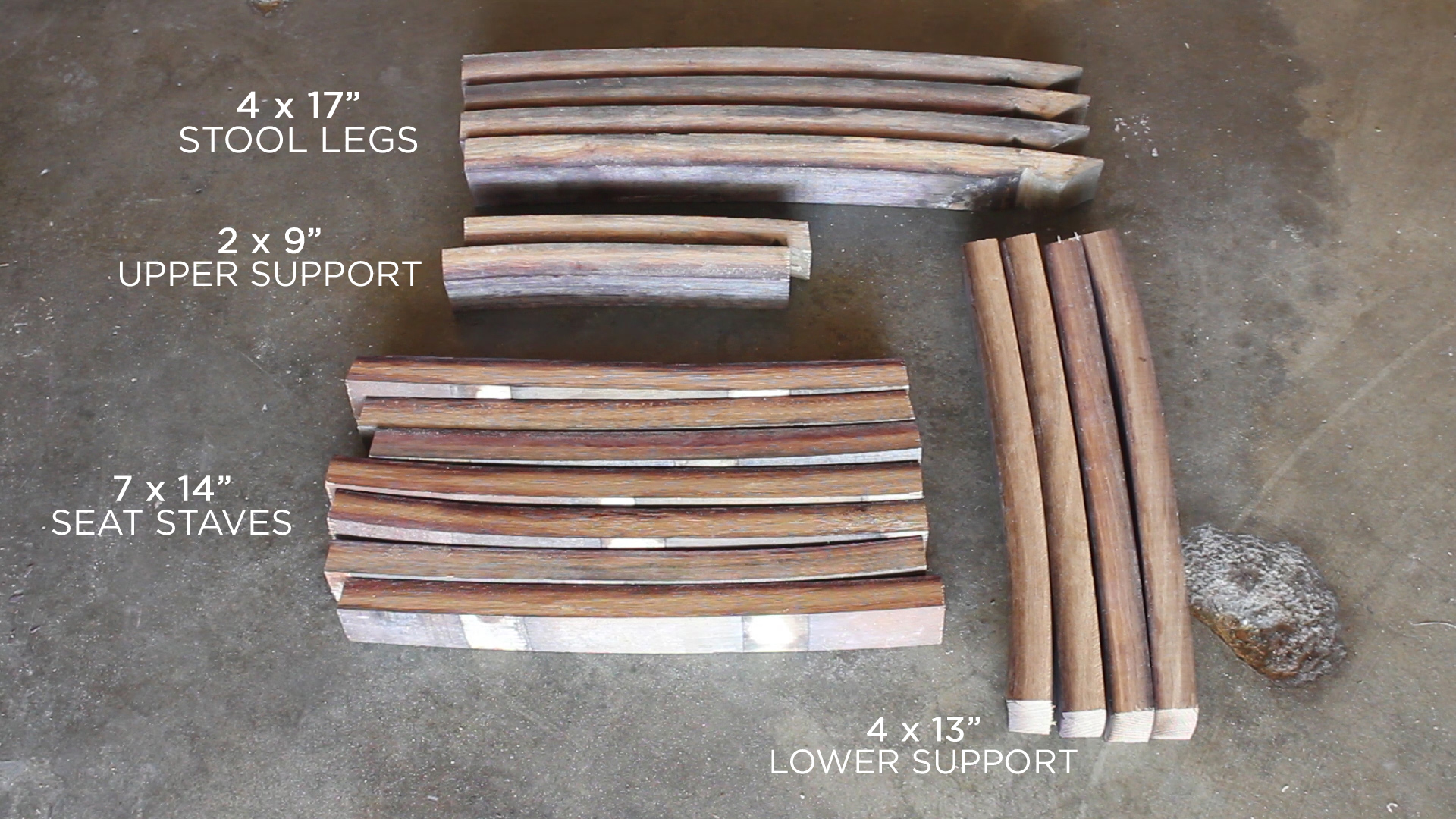
Here are my cuts with rough measurements which I cut on the spot based on my own mental design:

  • 4 x Legs (about 17" each) made from 2 x Staves
  • 2 x Upper Supports (about 8-9") made from half of 1 x Stave
  • 4 x Lower Supports (about 14") made from 2 x Staves
  • 7 x Seat Staves (about 14") made from 3.5 x Staves

Now it is Assembly Time!

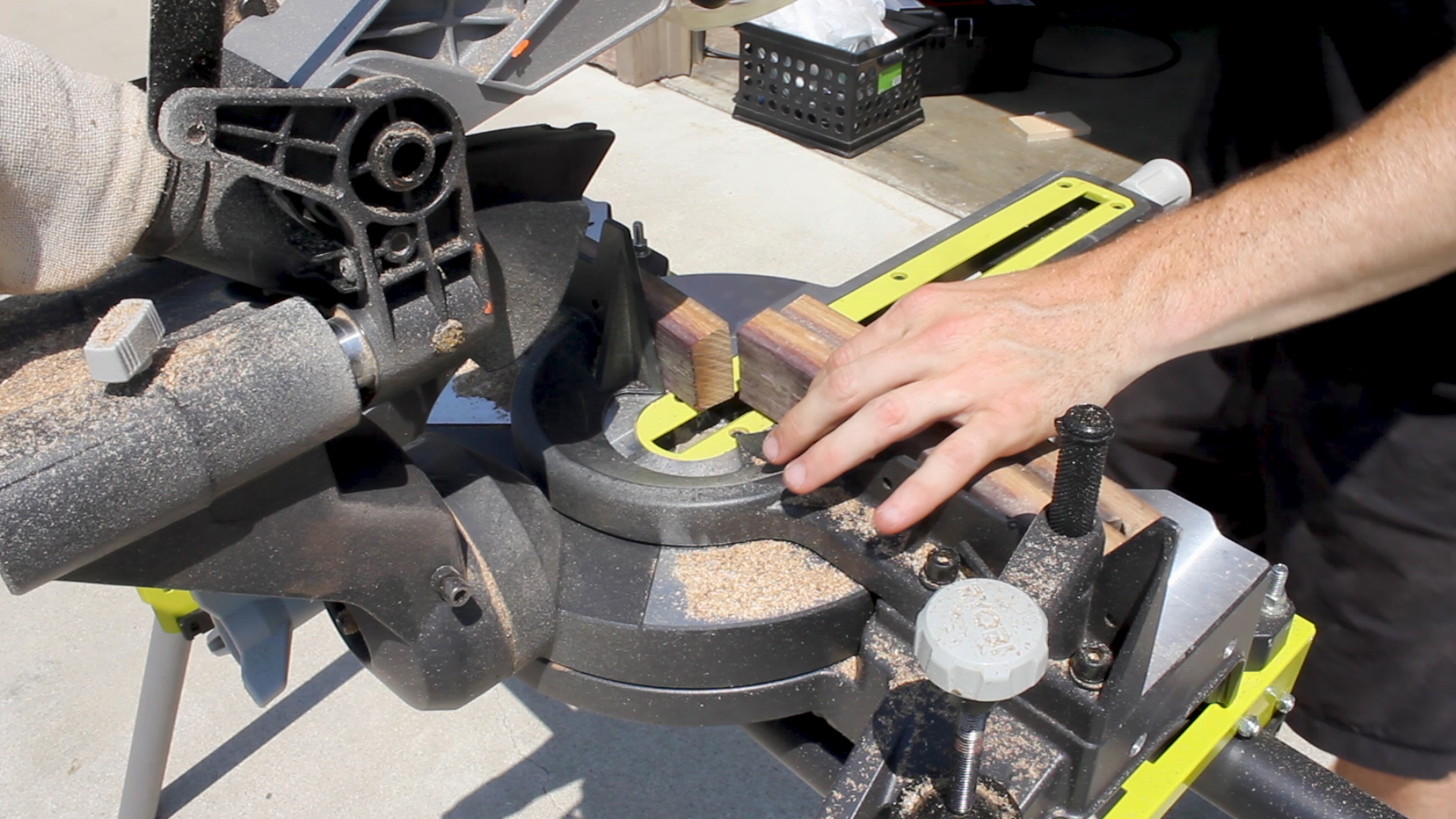
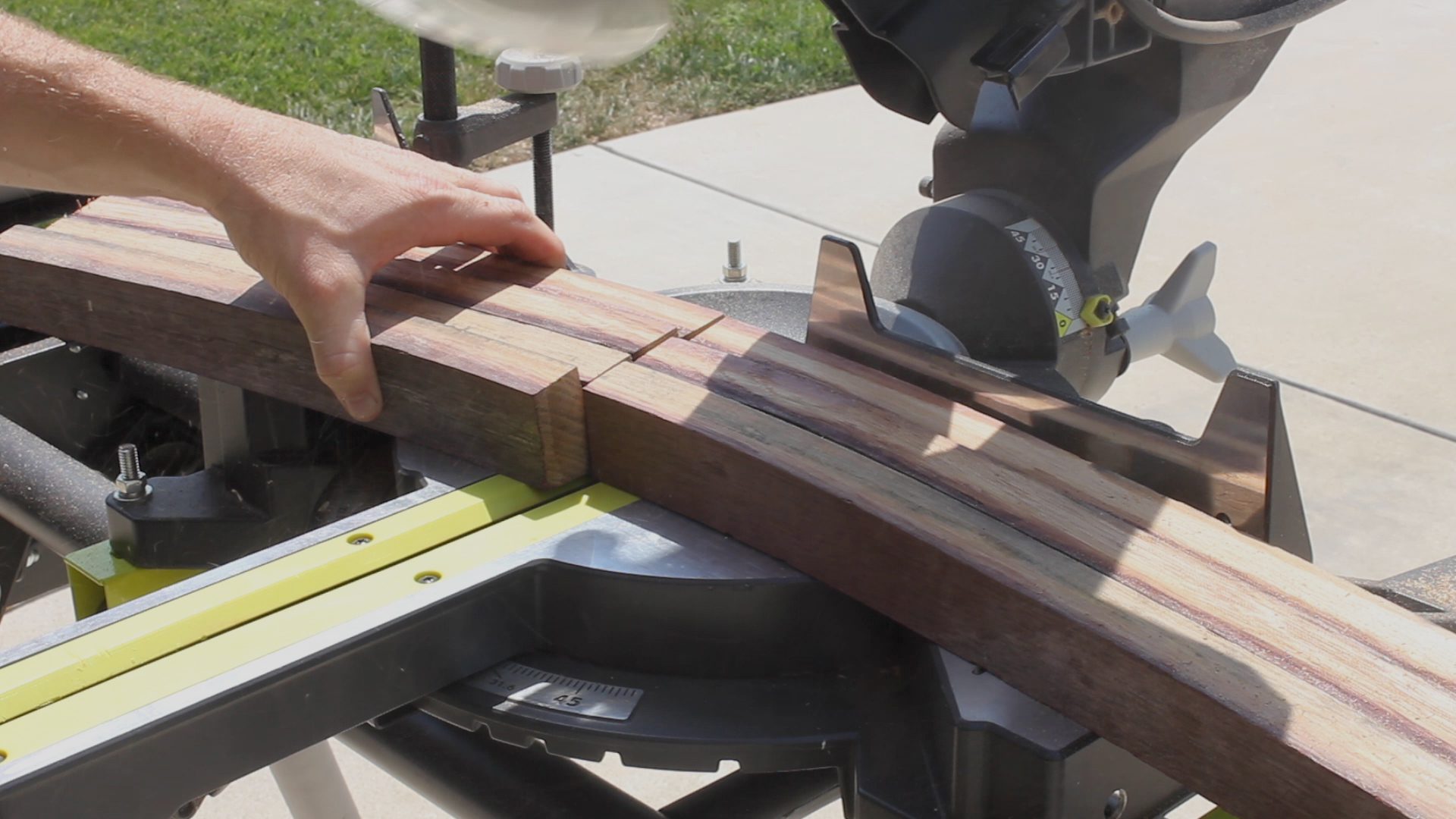
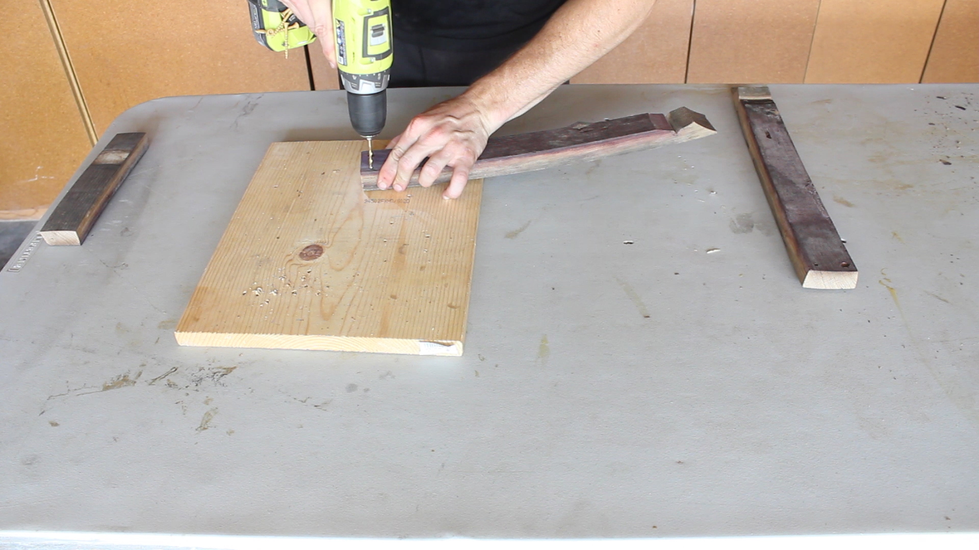
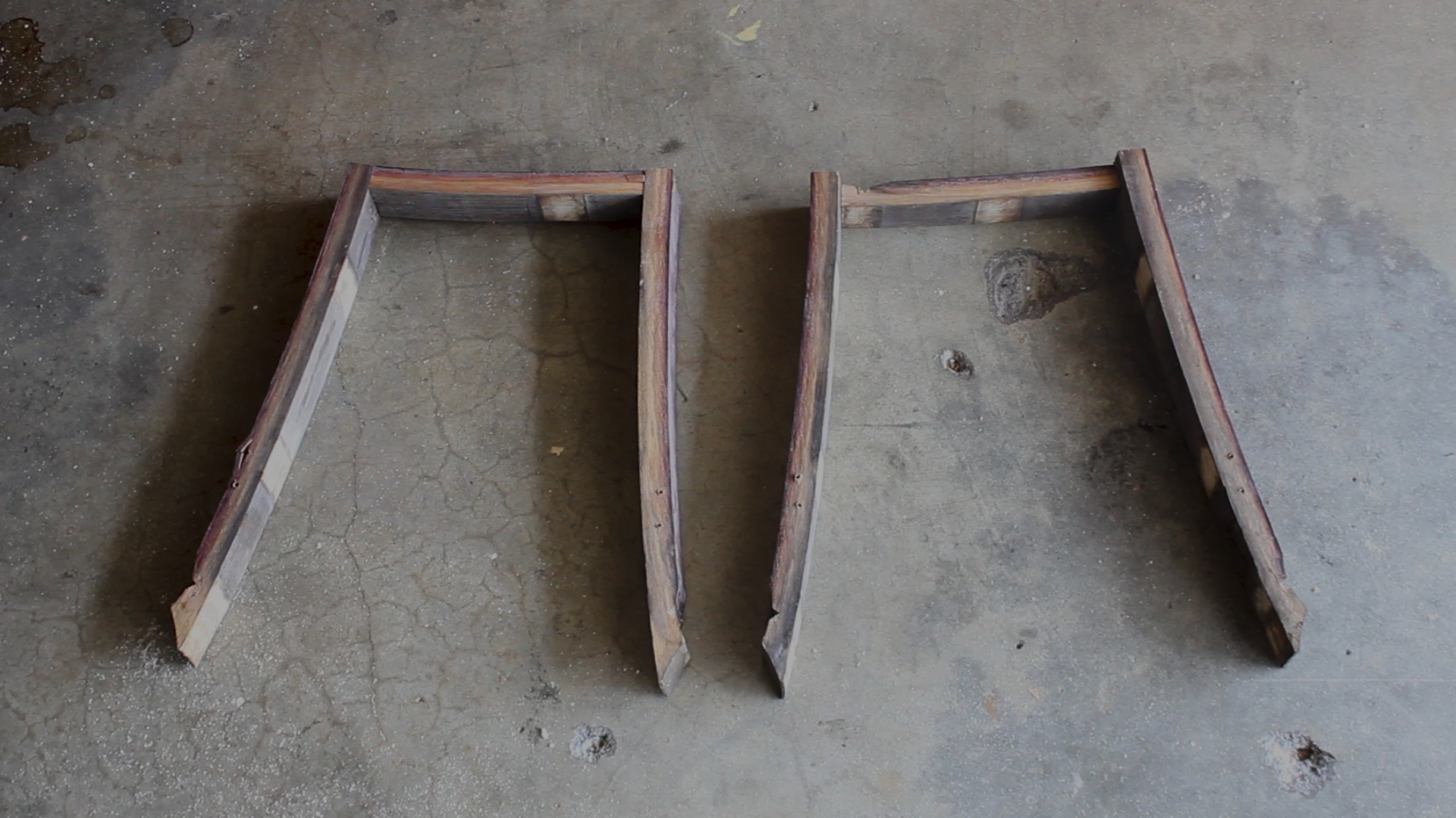
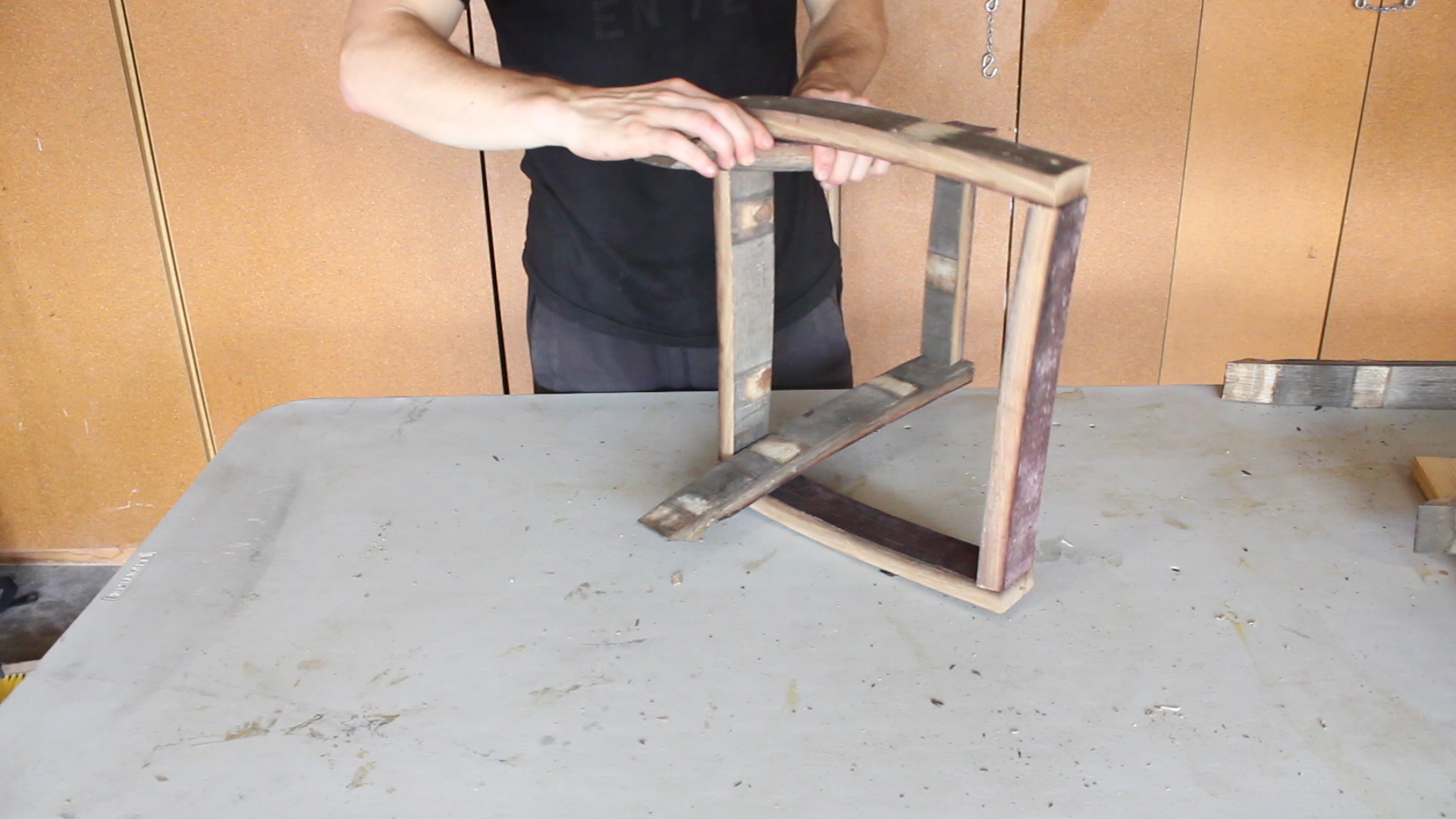
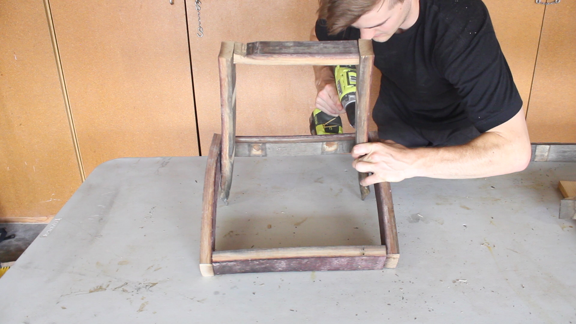
Note - I pre drilled all of my holes before screwing in screws to avoid the wood splitting. It's old - didn't want to risk it. I started by making my to legs pieces using one upper support and two legs for each piece. The last picture shows the final design. 

Assembly Part 2.

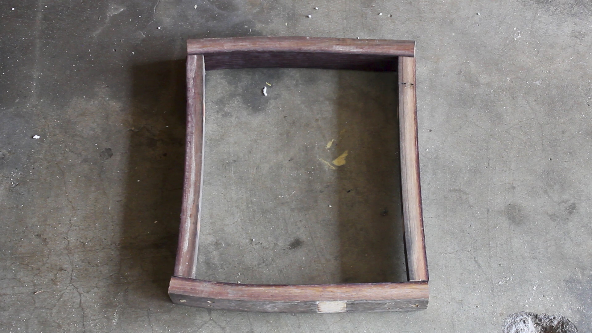
I took my four lower supports and assembled them. Two pieces were turned out, two were turned in - this was to make the bottom supports fit around the legs - see the next step for clarity. 

Assembly Part 3. 

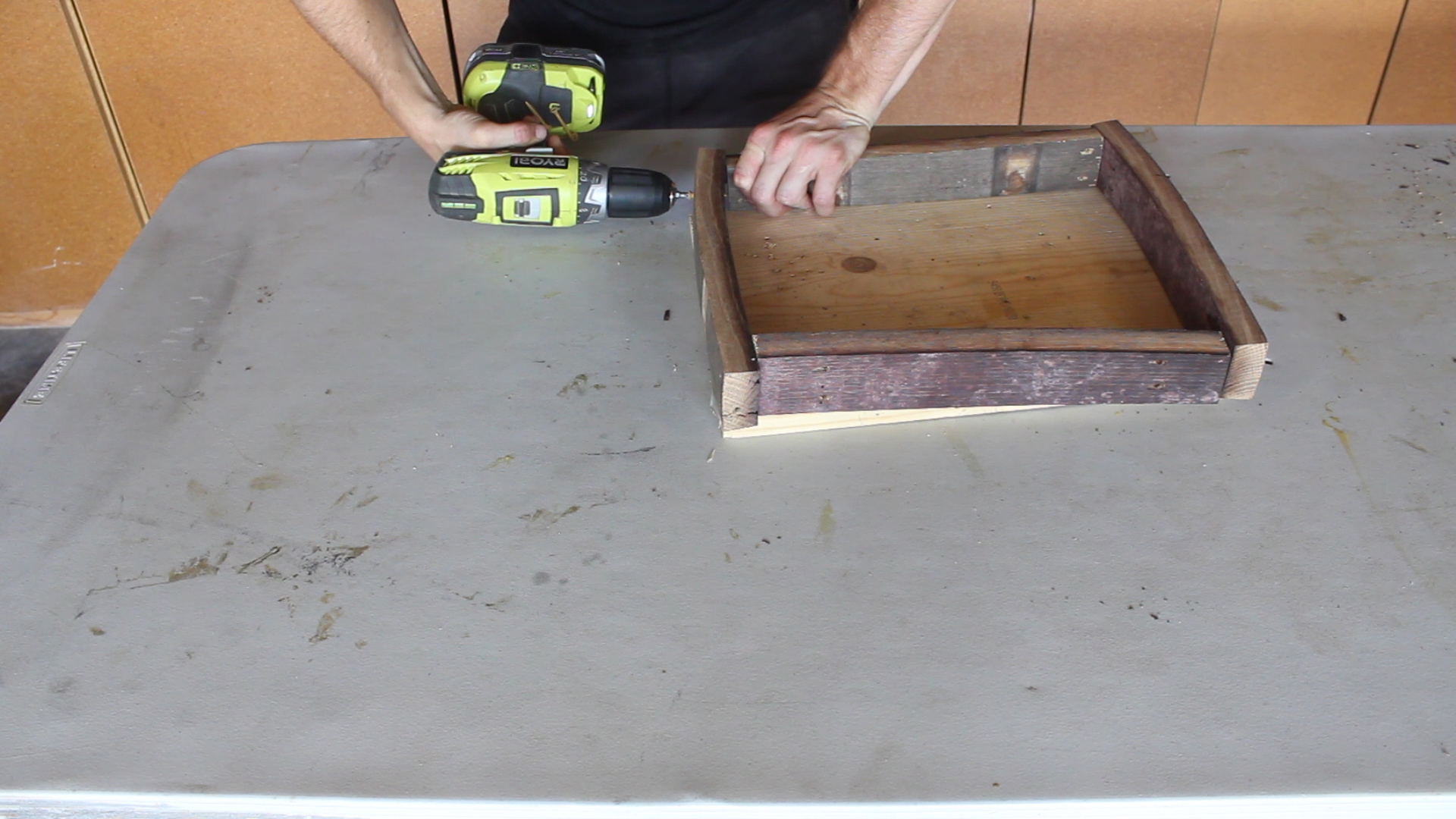
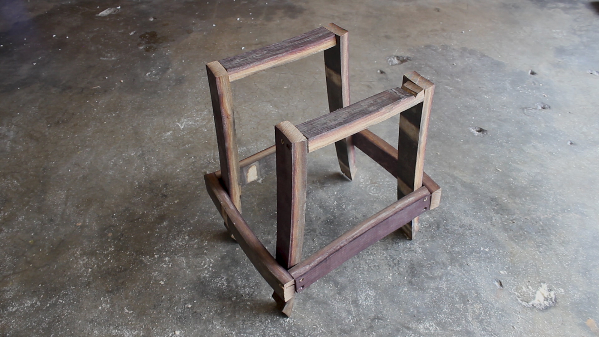
I then combined Assembly Steps 1 and 2 as such. You can see that the legs pieces were wedged in between the bottom supports with the wider part of the leg faces facing the inward facing staves. This is how the design comes together to be very strong and even. 

Assembly Part 4.

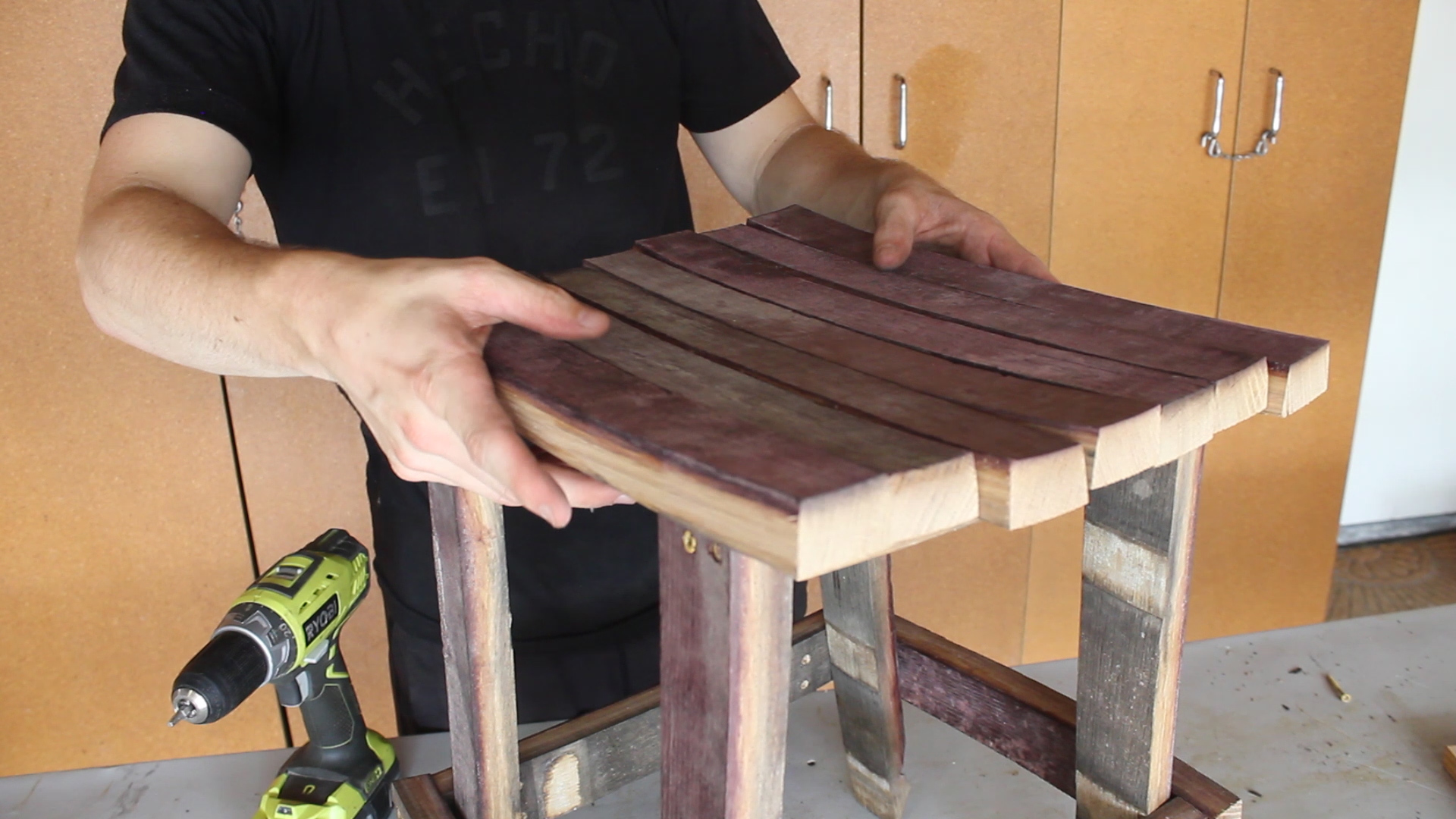
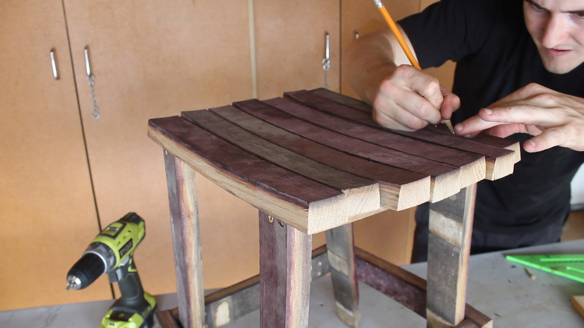
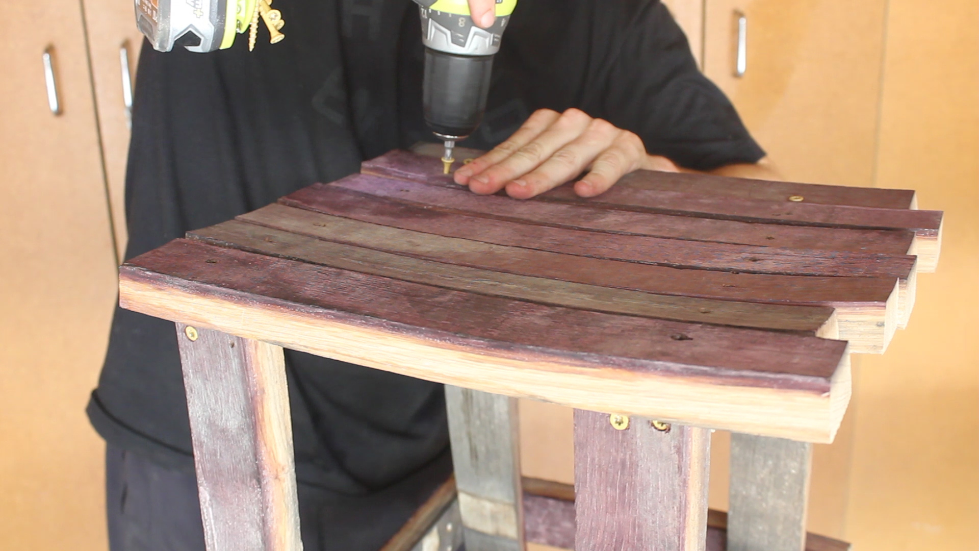
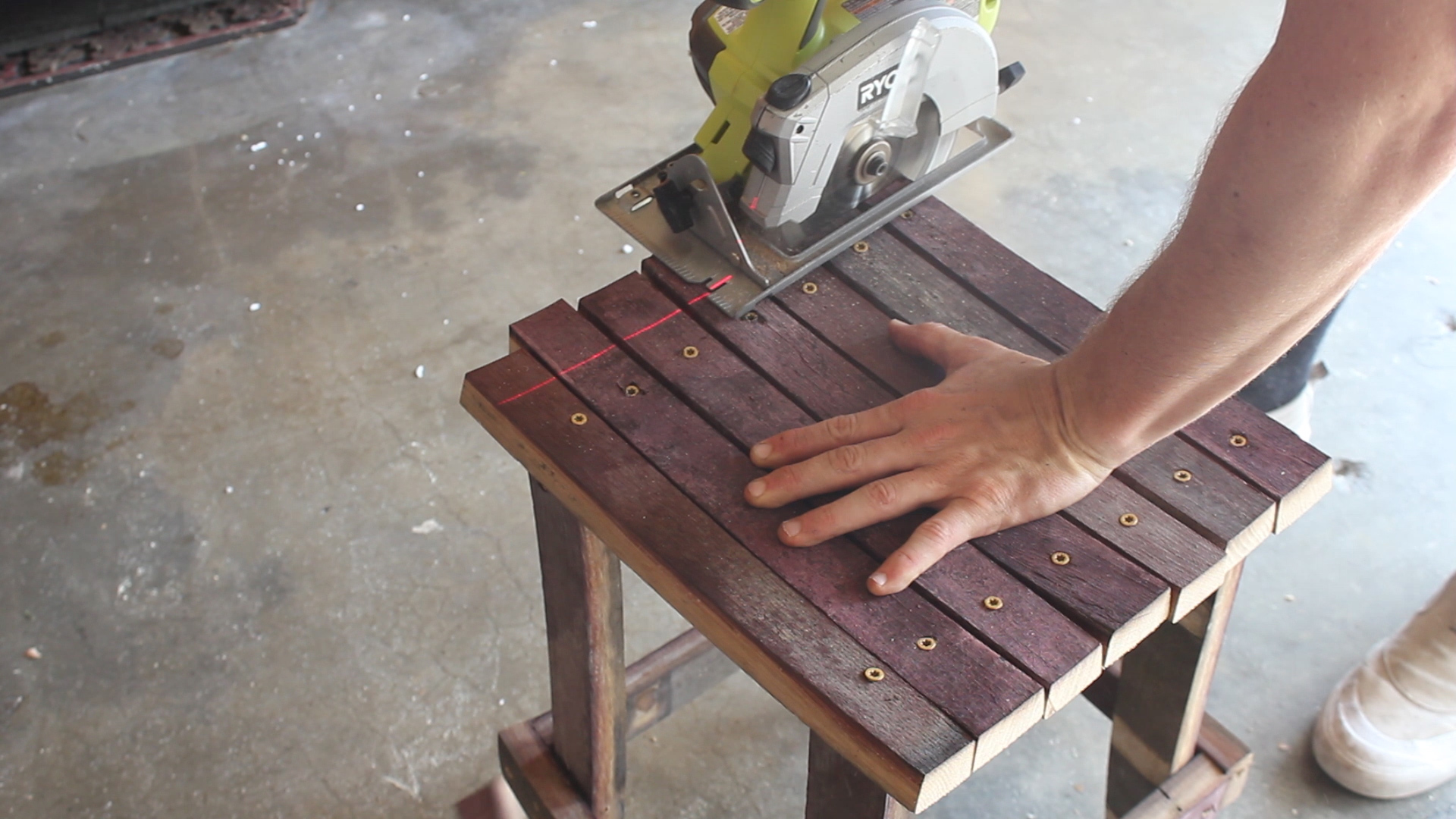
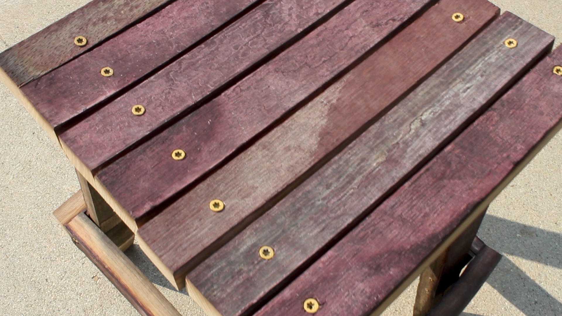
I attached my 7 x Seat Staves to the top of the legs using pre drilled holes and the asme wood screws. I made sure to square up one side so that I could just square up the other with a circular saw once it was all attached. The staves are not going to be the same sizes, so just run with it - it will be unique - just like you!

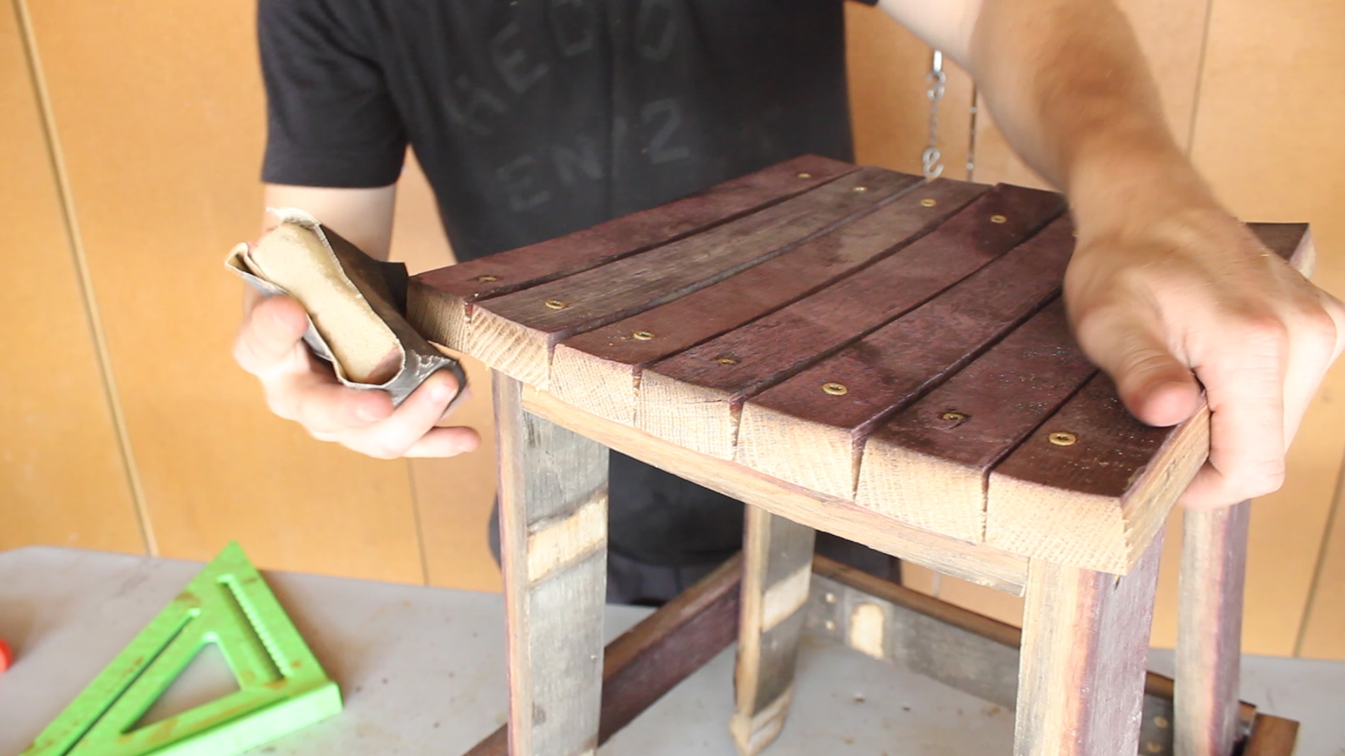
As stated before, I then used my circular saw to square up the other size and lightly sanded down my edges with some 120 grit paper. 

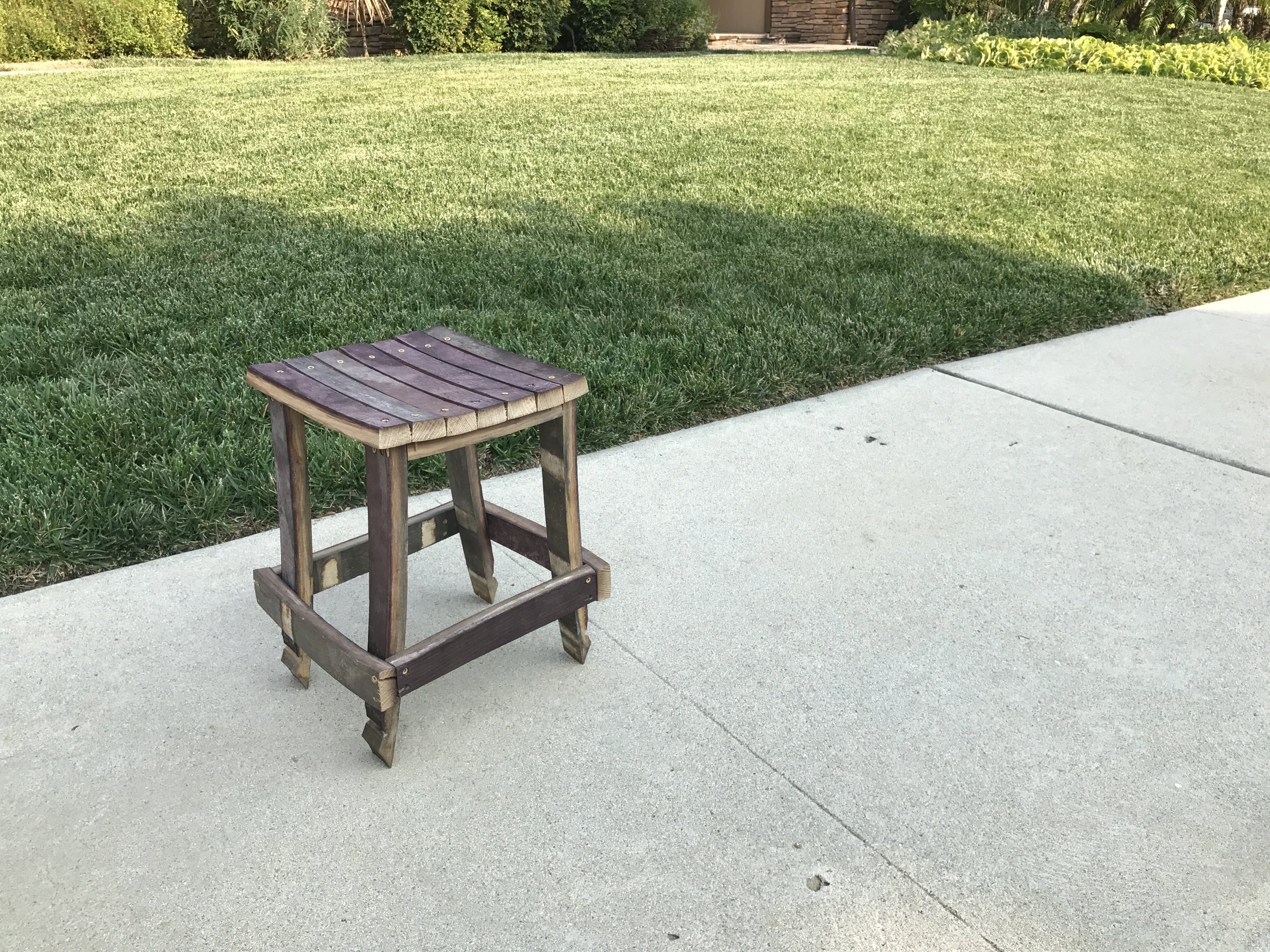
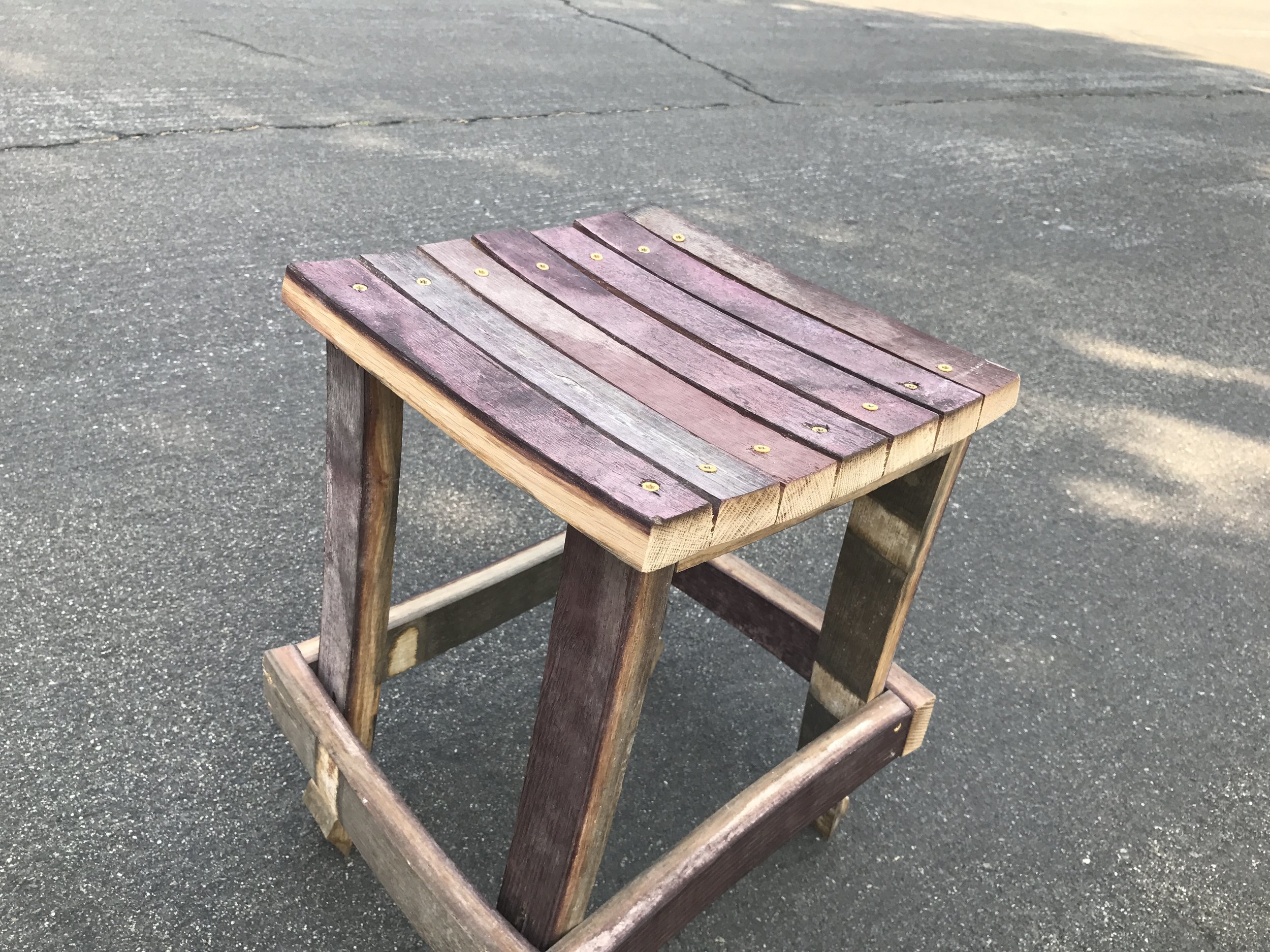
At this point, the stool was done. There are a few things I could do to it additionally, such as put a sealant on it or really round over the edges. I might do that at some point, but for now, the stool looks great, is very sturdy, and I'm proud of my afternoon project!

Final pics below!

YT Thumbnail - No Text.jpg

TOOLS
RYOBI 10 in. Sliding Compound Miter Saw
RYOBI Miter Saw Stand
RYOBI Power Drill
12” Rafter Square
RYOBI Drill Bit Set
Hand Sanding Sponges  

As always, thank you for reading! I would be so grateful if you could please subscribe to my Youtube Channel for future projects. I put out videos every few weeks.

Cheers!

Zach


Hardwood Wine Bottle & Glass Holder


THANKS FOR CHECKING OUT THE FULL ARTICLE!
PLEASE SUBSCRIBE TO OUR YOUTUBE CHANNEL BY CLICKING HERE.

My full video of the build is below, followed by detailed instructions with tools, materials, and measurements! 

I'm slowly moving into doing finer woodworking / crafting. It means more precision, more attention to detail, and using tools I am still a beginner with. It means going slower in the process, but creating something I'm proud of. My mom wanted me to make her a few wine bottle / wine glass holders as future Christmas gifts. I saw it as a fun opportunity to work with lots of hardwood species!

MATERIALS

1.jpg

Use any material you want. I wanted variety, and I knew what tools I had on hang, so I went with five different species for my build. I had Ipe and Walnut scraps, and I purchased Maple, Mahogany, and Poplar. All wood is about 4/4 stock in thickness and 2 feet in length. 

2.jpg

I didn't have a huge amount of methodology to how I ripped my strips, other than that no piece would be wider than 2" and no thinner than 1/4", and I would try to mix up the variety as much as possible. 

SUB---SNAP.gif

Once you have all your strips cut and the surfaces are clean for gluing (should be fine coming off the table saw), mix them up how you want to and get ready for the glue up.

Nothing special here. I applied enough glue to spread out and cover all of my surfaces. Keep it flat as you clamp up, and let it dry overnight. I used an old card to spread my glue, and I do my glue ups on top of a flat piece of plywood covered in masking tape to avoid any sticking.

After your glue up dries, you can run it through the planer a few times to clean up all of your surfaces. I tried to keep the final thickness at least 1/2", but that will be based on your starting material size. Next, I cleaned up one edge of the large blank and I ripped my blank into four pieces, all 4.5" wide. 

I marked out a center hole and two holes on each end that would accept a wine bottle and wine glasses, respectively. The center of the two outside holes were 1.25" in from the outsides, and I used a 7/8" forstner bit to drill those holes. Make sure you secure your piece firmly to your surface with a clamp.

I then drilled the center hole with a 1.125" forstner bit. Once all of my holes were drilled, I use my miter saw to make two cuts, creating alternating grooves to the two wine glass holes. Pretty straight forward, just make sure you're piece is secured and you take the cuts slow. You can see in the last picture how those grooves come together. 

NOTE - If you plan to route your edges, make sure that you cut these slits wide enough so that your router bit and bearing can travel through it cleanly.

You can make these any shape you want. Pic 1 shows me using some scrap edge banding and tape to create a smooth line to cut later. Pic 2 shows me using a circle to create rounded edges. I then roughed everything out on my super awful band saw that I need to replace (Pic 3).

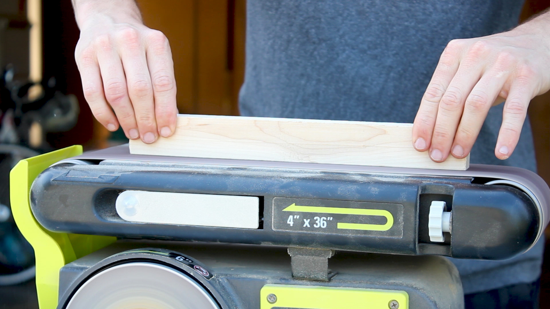
I then switched to my stationary belt sander in Pics 4-6 and smoothed over all of the edges, corners, and surfaces using 80 grit on the sanding disc and 120 grit on the belt. I also used new discs and belts for this - something I learned makes the world of a difference for just a few bucks!

I used a 1/4" round over bit and my palm router (Pic 1) to break all of the edges. Pic 2 shows all the edges routed and the two shapes I created from my blanks in the previous step. I then did some final belt sanding of the rounded edges (Pic 3) and some wet and dry hand sanding (Pic 4) to finish these guys off.

I cleaned my surfaces with mineral spirits and then applied thick coats of mineral oil to all the surfaces to finish them off and bring out all of the colors. They looked beautiful!

Pic 1 shows the final wine bottle / wine glass holder (or at least one version), and Pic 2 shows how it functions!

Perfect for any date night or table / kitchen counter!

TOOLS

FILM / AUDIO EQUIPMENT

As always, thank you for reading! I would be so grateful if you could please subscribe to my Youtube Channel for future projects.

I put out videos every few weeks.

Cheers! Zach


Concrete Charcuterie Board with Live Edge Inlay


THANKS FOR CHECKING OUT THE FULL ARTICLE!
PLEASE SUBSCRIBE TO OUR YOUTUBE CHANNEL BY CLICKING HERE.

My full video of the build is below, followed by detailed instructions with tools, materials, and measurements! 

This project is pure experimentation - I wasn't sure how it'd come out.

Spoiler - it was a decent success. It was my second concrete project ever, and it was a step forward in advancing my maker skill set. I guess you could chalk it up to wanting to try mixing resources with the fact that I already had most of the materials on hand.

MATERIALS
Quikrete 5000 (~1/5th of a bag) - I also recommend Quikrete Countertop Mix
Melamine (for molding)
Scrap MDF (for Log Planer sled - not necessary if you have a band saw!)
Black Silicone Sealant: http://amzn.to/2zEOLHG
Minwax Fast Drying Spray On Poly: http://amzn.to/2heLF1z
Paste Wax (Any type)
Mineral Spirits (Any type)
Screws
Masking Tape: http://amzn.to/2pygofL
Container for Mixing Concrete (Use a big bucket!)

TOOLS
RIDGID 13” Thickness Planer: http://amzn.to/2u7YrmK
RYOBI Circular Saw: http://amzn.to/2q1l5wn
RYOBI Power Drill: http://amzn.to/2q1l5wn with Drill Bits
RYOBI 10 in. Sliding Compound Miter Saw: http://amzn.to/2q1klHw
RYOBI Miter Saw Stand: http://amzn.to/2p1072e
RYOBI Stationary Bench Sander: http://amzn.to/2q1Cq8k
RYOBI Glue Gun: http://amzn.to/2uLJt7V
Silcone Caulking Gun
Cake Fondant: http://amzn.to/2haxI4R
Any tools to vibrate the concrete: http://amzn.to/2q1l5wn
BESSEY Clamps: http://amzn.to/2oIJGVy
Hand Sanding Sponges: http://amzn.to/2oHa6pP
Level (24”): http://amzn.to/2phF3Cj
12” Speed Square: http://amzn.to/2phZUIt

FILM / EDIT EQUIPMENT:
Canon Rebel EOS T2i: http://amzn.to/2pwwlDI
Main Lens: Canon EF 50mm f/1.8 STM Lens: http://amzn.to/2zt0jKR
Secondary Lens: Canon EF-S 18-55mm f/3.5-5.6 IS II Lens:http://amzn.to/2pwmuhi
USCAMEL Tripod: http://amzn.to/2hbbVdg
Studio Lighting Equipment: http://amzn.to/2rtrkg0
Rode Microphone: http://amzn.to/2oIExg3
Blue Snowball Mic (VO Recording): http://amzn.to/2hd92sF

I found this old piece of firewood (Alder?) that was many years old and very dry and destined to be burned (Pics 1-2). I couldn't let that happen. Time for a fun live edge project (a first for me).

I used some scrap MDF and some wood screws to work up the simplest sled possible so that I could feed the log through my planer to start flattening (Pics 3-4). This was by no means the most efficient way to do this, but I don't have a band saw to mill lumber so this was my best option. Other options would be to just buy a small live edge slab, use a table saw jig of some type, or use a band saw if you have access to one.

I made many passes through my planer with the log in one position (I'd say 25-30) in Pic 1 to get to a nice clean flat surface in Pic 2. Then, I could flip the log over and over again, making incremental passes (Pic 3) until I was happy with the thickness of the piece, which was roughly half an inch. I wanted both sides to be very clean so I could later pick which side I liked best to be featured. Then I squared up both sides carefully (Pic 4) on the miter saw and was left with a perfect small live edge slab.

I wet and dry sanded down my piece up to 220 grit (Pic 1) and then applied a few coats of fast drying spray on Poly to my log (Pics 2-3) and sanded down to a smooth final surface. This was to water proof the slab so it wouldn't be damaged against the wet concrete. It is food safe once it dries.

Next, I pre-drilled (Pic 4) six holes, then inserted a few small screws (Pic 5), leaving me with a log that had screws in it Pic 6. These screws would serve the purpose of anchoring the log into the concrete so it was secured once the concrete cured.

I had scrap pieces of walnut from a previous build that I wanted to use as the legs (Pic 1). I routed a chamfer on the edge (Pic 2), which wasn't very clean, so I cleaned it up on the belt sander (Pic 3). Easy enough.

I then cut my pieces to length in Pic 4, a length that was based on the overall size of my molding. It is purely subjective to how you do this step. I cleaned up the sides in Pic 5 on the disk sander to create perfectly even lengths, and then applied the same poly sealant like I did to the live edge slab in Pic 6.

I then did the same anchor screw method in Pics 7-8, leaving me with two ready-legs in Pic 9. I think they look pretty cool!

Using the final size of my live edge slab (totally unique to your situation), I then cut a base and four sides for the base out of melamine to fit the slab (Pics 1-2).

Then, using hot glue (Pic 3), I built the molding. You can use screws here if you want to reuse the mold, but i find hot glue to be quicker, just as secure, and I didn't plan to reuse the mold.

Once you build your mold, take paste wax (any brand) and spread it around all of the corners of your mold (Pics 1). Then, using a caulk gun, spread black silicone sealant around all of the edges and corners of your mold (Pic 2). Using a simple cake fondant tool (Pic 3 - link to this product in Step 2), you can run the small circular end over all of your edges leaving you with really nice, rounded edges (Pic 4).

Once the sealant cures after about 30 min, you can go back and peal off all of the excess that it created (Pic 5). You are able to do this very easily due to the paste wax you spread out earlier. Once you've pulled off all the excess, go back with mineral spirits (I had a small amount in a water bottle - Pic 6) and wipe off all excess paste and clean up the mold.

Now you're ready to cast!

I used my Speed Square (Pic 1) to measure 1.25" from the bottom to serve as an indicator of how high I should pour my concrete (again, totally subjective to your own build). I also checked to make sure the ground I was working on was level (Pic 2). It wasn't, so I later shimmed my mold.

Off camera, I also covered the TOP of my slab in painters tape. That way, the concrete couldn't get on the mold incase some got underneath (Pic 3). I also gathered all my materials to cash. I mixed Quikrete 500, water, and stirred up the mix in an hold laundry detergent container (Pics 4-5) and then poured in my mold (Pic 6).

OPTIONAL  Tape down your slab to the bottom of the mold using double sided tape.

TIP 1  Use a large bucket to mix concrete all at once - I had to do this 4 times to fill my mold entirely - and I know for a fact that each pour had different consistencies in the concrete.

TIP 2  If you're looking for a very fine concrete, you should look to get Quikrete Countertop mix or use a sifter to filter out the larger rocks of the mix. I wish I had done this, but it was a learning experience nonetheless.

Once I poured my mold, I shook the mold back and forth quickly to spread things out and used a tool to vibrate the bubbles (Pic 1) - you can use anything you have for this - a sander, a multi tool, etc.

Having checked before that the ground was not level, I knew to shim up my mold 1/8" on one side to keep it level (Pic 2).

I worked up a little contraption in Pic 3 that allowed me to suspend my two legs into the concrete while it cured. Just scrap wood and hot glue - and I was very careful to check that everything was even and square. I had put in a lot of work at this point - no need to mess up now! I checked for evenness in Pic 4.

PRO TIP   Your molding tops might not be level - MINE WERE NOT. You can see in Pic 4 how the right side has two pieces of foam to prop up the contraption. If your molding is not even like mine, your legs will not sit level in the mold and will cure at a slope, So check for this levelness ahead of time.

I let the concrete cure for a full two days.

Once it did, it was rather easy to break apart the mold and pull the casting out of the concrete (Pic 1). I then pealed away the tape eagerly to reveal a very clean live edge top (Pic 2).

I realized after casting that I should have taped off the sides too, but was able to clean up the sides really easily with a chisel in Pic 3. I then used some wet sand paper at 220 grit to sand down all of the surfaces and edges in Pic 4. I took my sweet time with this. The concrete wasn't fully cured, but was perfect for sanding down.

You can see in the close up of the pictures that there were bubbles and other imperfections. Three things would help prevent this:

  • Better bubble vibration to get rid of air pockets
  • Using a finder concrete mix
  • Mixing concrete all at once in a big container

Here are various photos of the final product - both overall and in detail. Many ways to improve, and I intend to do so soon!

As always, thank you for reading! I would be so grateful if you could please subscribe to my Youtube Channel for future projects. I put out videos every few weeks.

Cheers!

Zach


Woodworking Up-cycle of a Tea Kettle


THANKS FOR CHECKING OUT THE FULL ARTICLE!
PLEASE SUBSCRIBE TO OUR YOUTUBE CHANNEL BY CLICKING HERE.

My full video of the build is below, followed by detailed instructions with tools, materials, and measurements! 

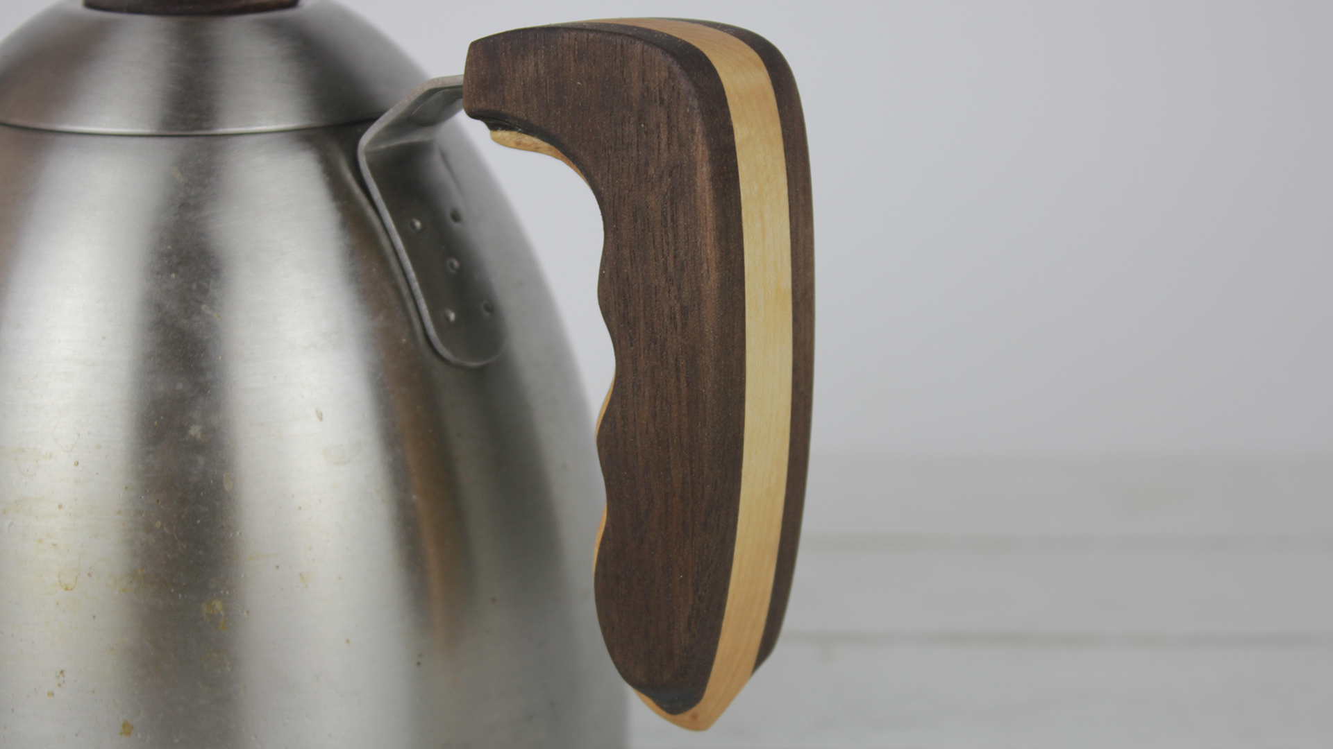
I have a gooseneck tea kettle we use for making coffee-pour overs. It works great, but it is very basic. I felt like making it a little bit better (12% to be exact). Hope you enjoy this little fun project. I obviously made mine a bit more complicated by using multiple woods, etc, but you can do it quite easily with just a single piece.

I went all out on this one, using pretty much everything I had in my arsenal to make something so simple. I'm sure there are easier ways to do it (no planer, no band saw, no router), but I did it this way. I leave it to you to figure out the best method to up-cycle your equipment!

MATERIALS
Scrap Walnut and Maple woods
TiteBond II Wood Glue: http://amzn.to/2peRFus
Mineral Oil: http://amzn.to/2p1hu2N

TOOLS
RIDGID 13” Thickness Planer: http://amzn.to/2u7YrmK
RYOBI 10 in. Sliding Compound Miter Saw: http://amzn.to/2q1klHw
RYOBI Miter Saw Stand: http://amzn.to/2p1072e
RYOBI Power Drill: http://amzn.to/2q1l5wn
RYOBI Stationary Bench Sander: http://amzn.to/2q1Cq8k
RYOBI Band Saw: http://amzn.to/2rYzJF8
BESSEY 2.5” x 12” Clamps: http://amzn.to/2oIJGVy
Digital Caliper: http://amzn.to/2p360xg
Vice Clamp: http://amzn.to/2q1GfKO
RYOBI Drill Bit Set: http://amzn.to/2oKKWXi
RYOBI Router Set: http://amzn.to/2pwx87Z
Hand Sanding Sponges: http://amzn.to/2oHa6pP

FILM / AUDIO EQUIPMENT
Canon Rebel EOS T2i: http://amzn.to/2pwwlDI
Canon EF-S 18-55mm f/3.5-5.6 IS II Lens: http://amzn.to/2pwmuhi
H4N Zoom Mic (VO Recording): http://amzn.to/2uMeVWL
Studio Lighting Equipment: http://amzn.to/2rtrkg0

I removed the two components I'd be replacing using just a screwdriver (Picture 1). I then traced (Picture 2) both components and took super detailed measurements just to have on hand (Picture 3) using various measuring tools (digital caliper, tape measure, etc.). These measurements were helpful in planning my scrap material search.

I had walnut and maple laying around (Picture 1). My maple was not wide enough to match my walnut, so I glued up / laminated (Picture 2) and clamped up (Picture 3) to pieces to let dry overnight.

The next day, I planed down the walnut strip to about .25" (Pictures 4 - 5) and the maple strip to about .50" (Picture 6). This was all based on a design I had in mind. If you're not gluing up anything, etc. and it is just a solid piece, you'l want to have clean scraps that will fit the size of whatever you're replacing.

Also, note the snipe in Pic 6 - still working out the kinks on my new planer.

I cut my walnut piece in half (Picture 1), as well as trimmed off the ends that had imperfections (Picture 2). Note - I kept these scraps as I figured I'd use them to help replace the lid top. More on that later.

Next, I laid out my final design - you can see how the maple strip was planed to be thicker than the two walnut strips to help make this pattern (Picture 3).I then glued up and clamped up (Pictures 4 - 5) to let my pieces dry overnight. Make sure you spread your glue evenly so everything is covered.

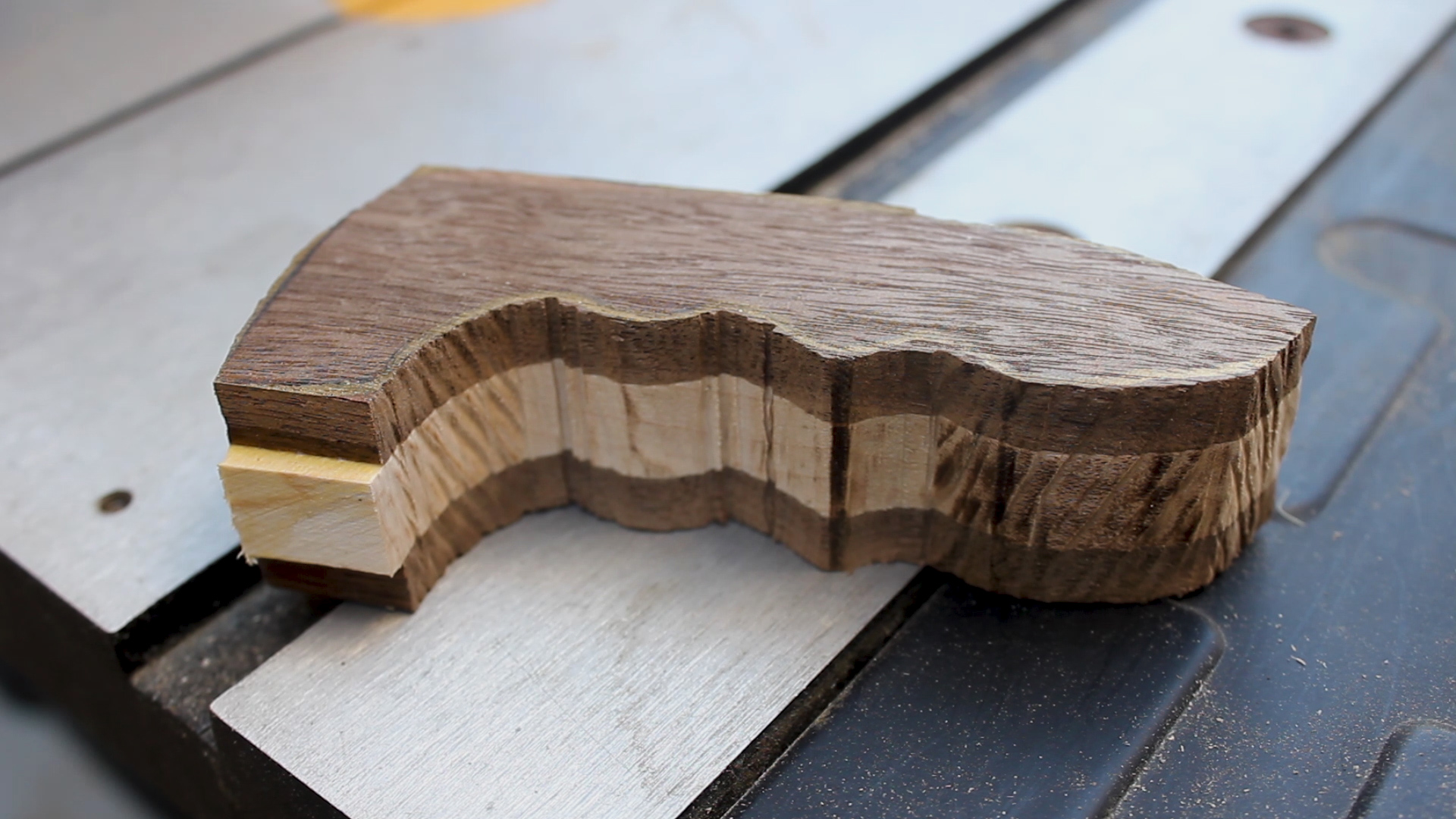
I took my drawings from earlier and revised them to a shape I thought was cool (Picture 1), and then cut them out (Picture 2). I transferred the design to my blank (Picture 3), and then cut out the blank using my band saw (Picture 4). Picture 5 shows the first pass at roughing it out.

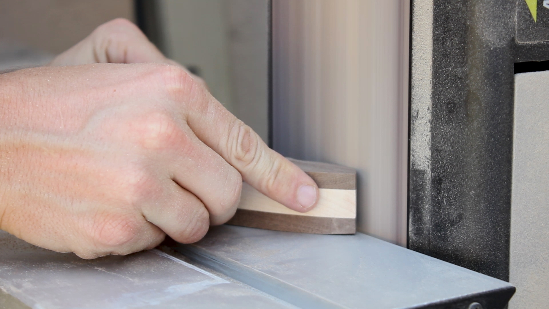
I cleaned up as many surfaces as I could using my stationary belt sander (Picture 1). There were quite a few areas I couldn't get into at this point. This was just to smooth out as many rough surfaces from the band saw blade as I could.

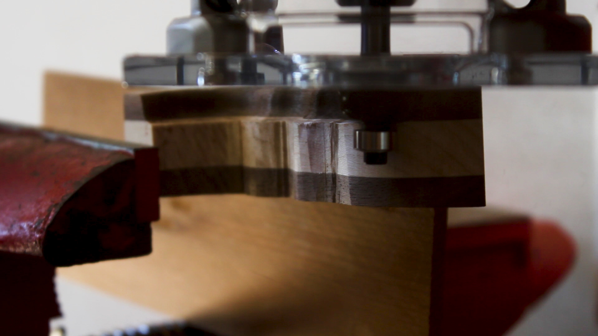
I then used my palm router and a vice clamp to route out a profile on the underside of the handle (Picture 2). I didn't know exactly how this would come out, but the goal was to make it more ergonomic to hold as well as help better highlight the different wood species.

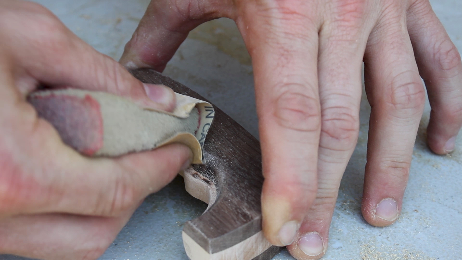
I cleaned up the rest of the piece, including the curves, any burn marks, and overall just rounded and smoothed over the piece (Picture 3) using some fine grit sand paper (I did this both as a wet and dry sanding to raise the grain and eliminate that issue down the road when the tea kettle got wet).

Picture 4 shows the final piece - you can see how everything was smoothed over (as best I could) and routed to make it easier to hold. Not bad right?

Again - I had no idea what this should look like, so I just experimented until I was happy.

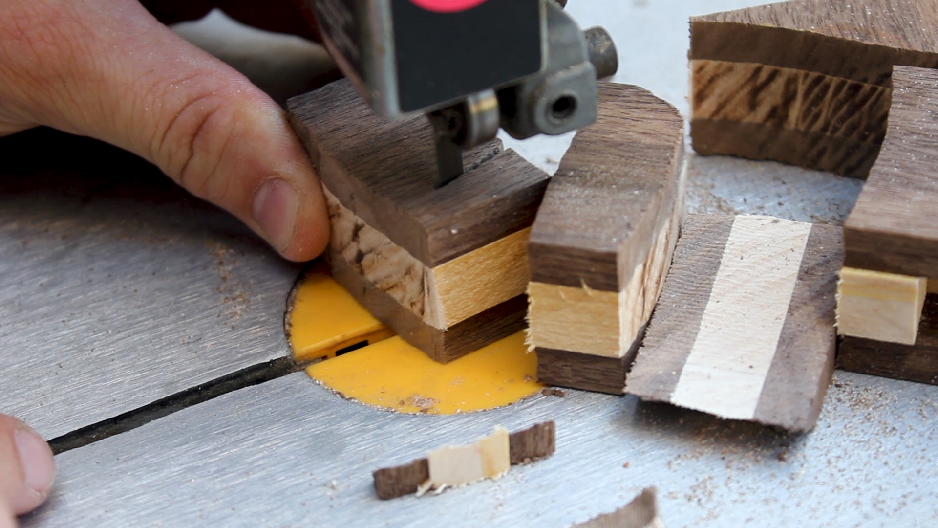
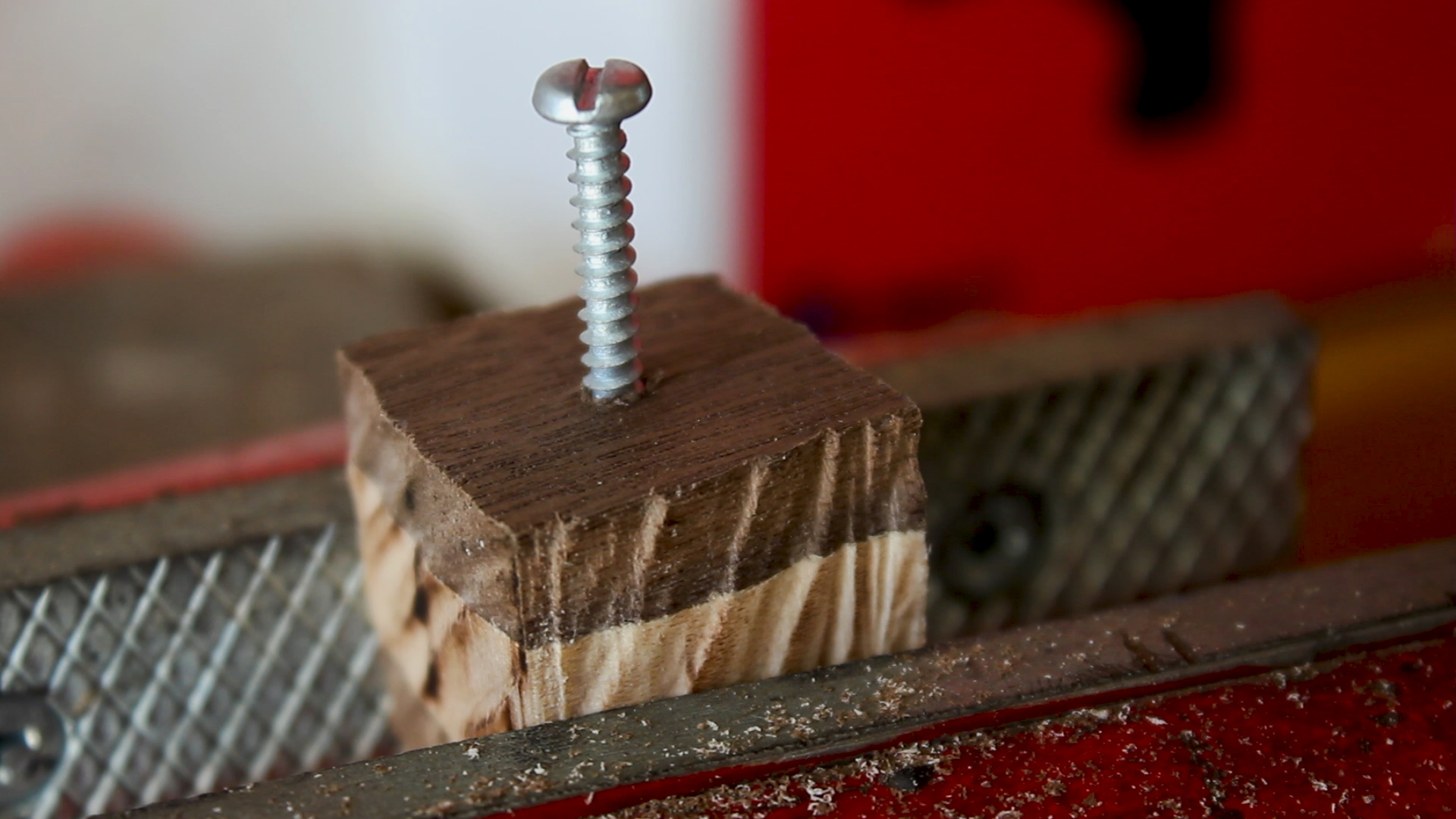
Pictures 1, 2, 3, and 4 show a sequence of me cutting out another small blank from left over glued up wood, drilling a pilot hole, inserting a screw, and putting that screw into my drill. My goal was to create a sanding lathe type thing using a drill and my stationary bench sander as I don't have a lathe to turn.

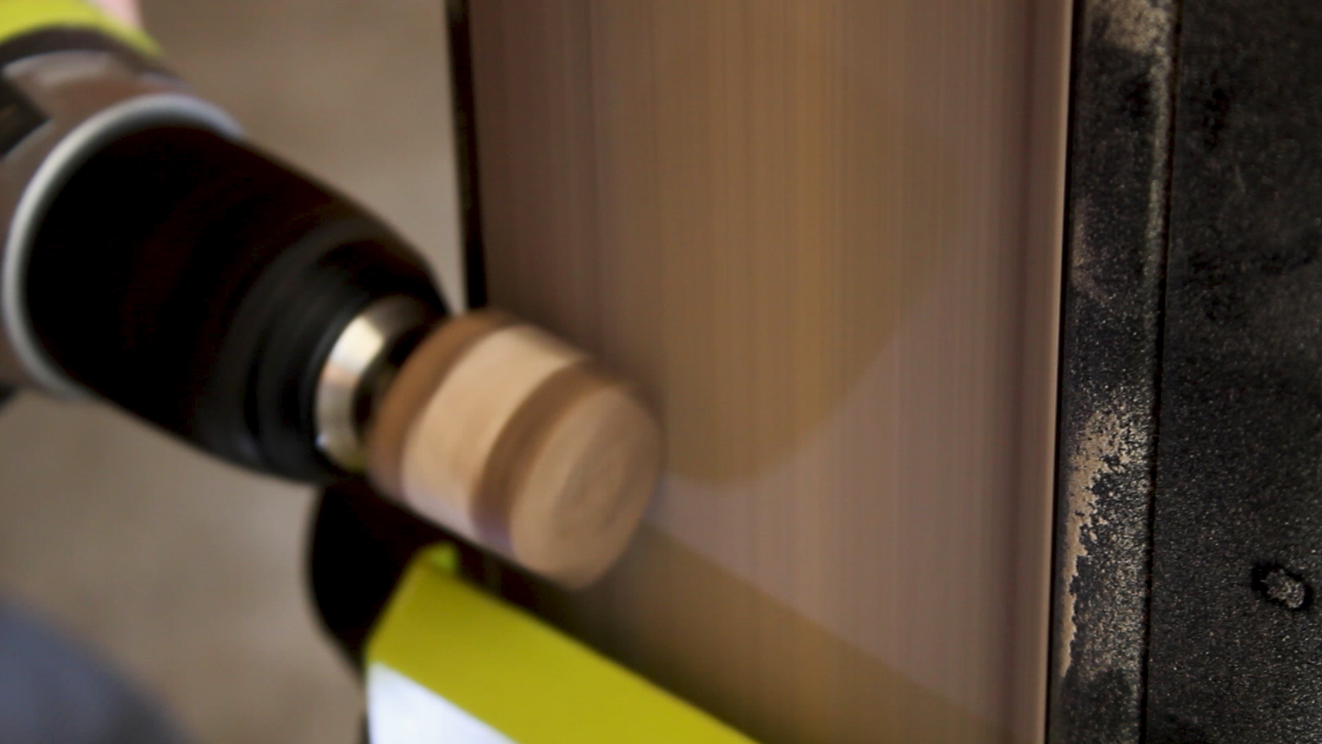
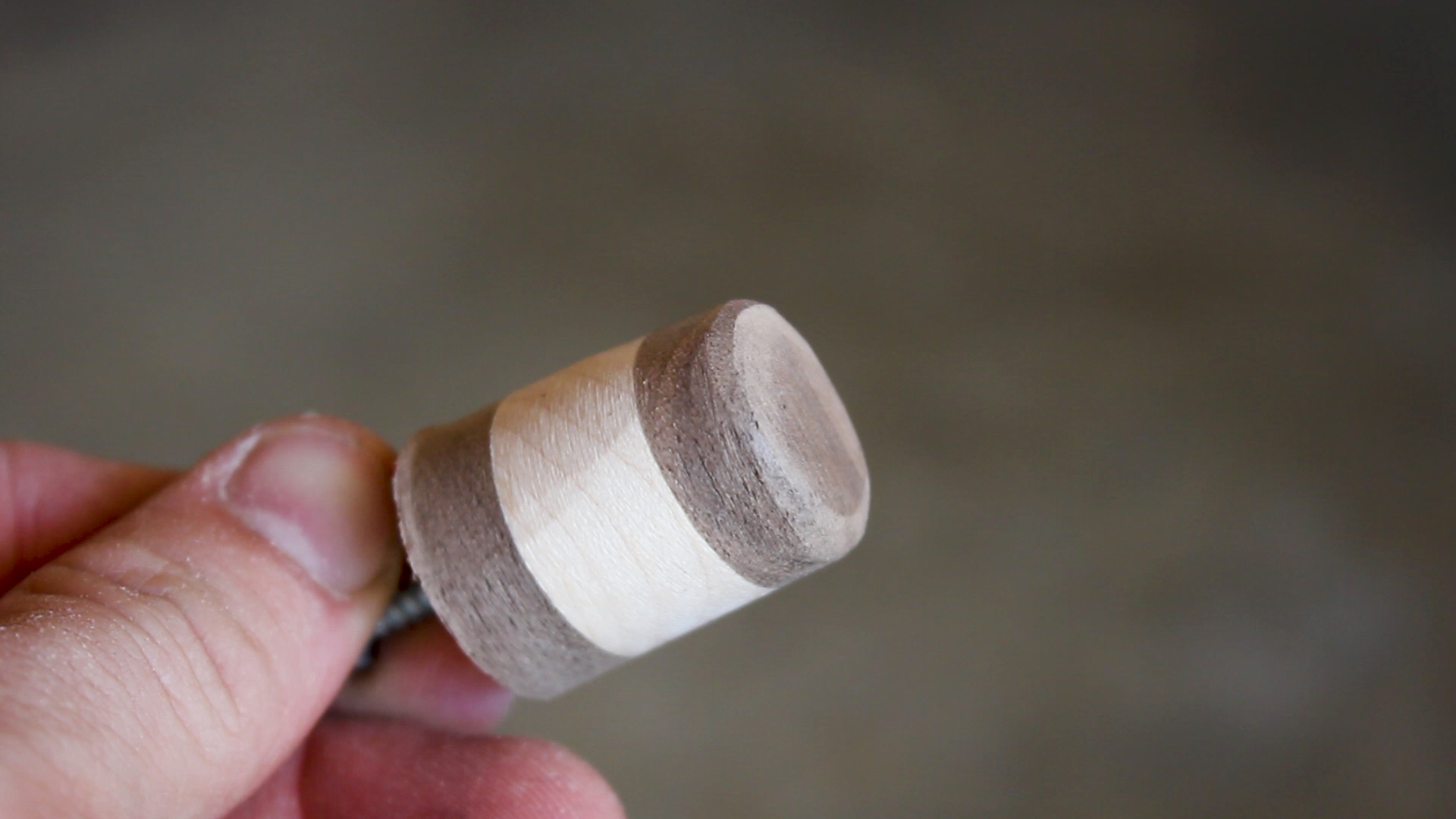
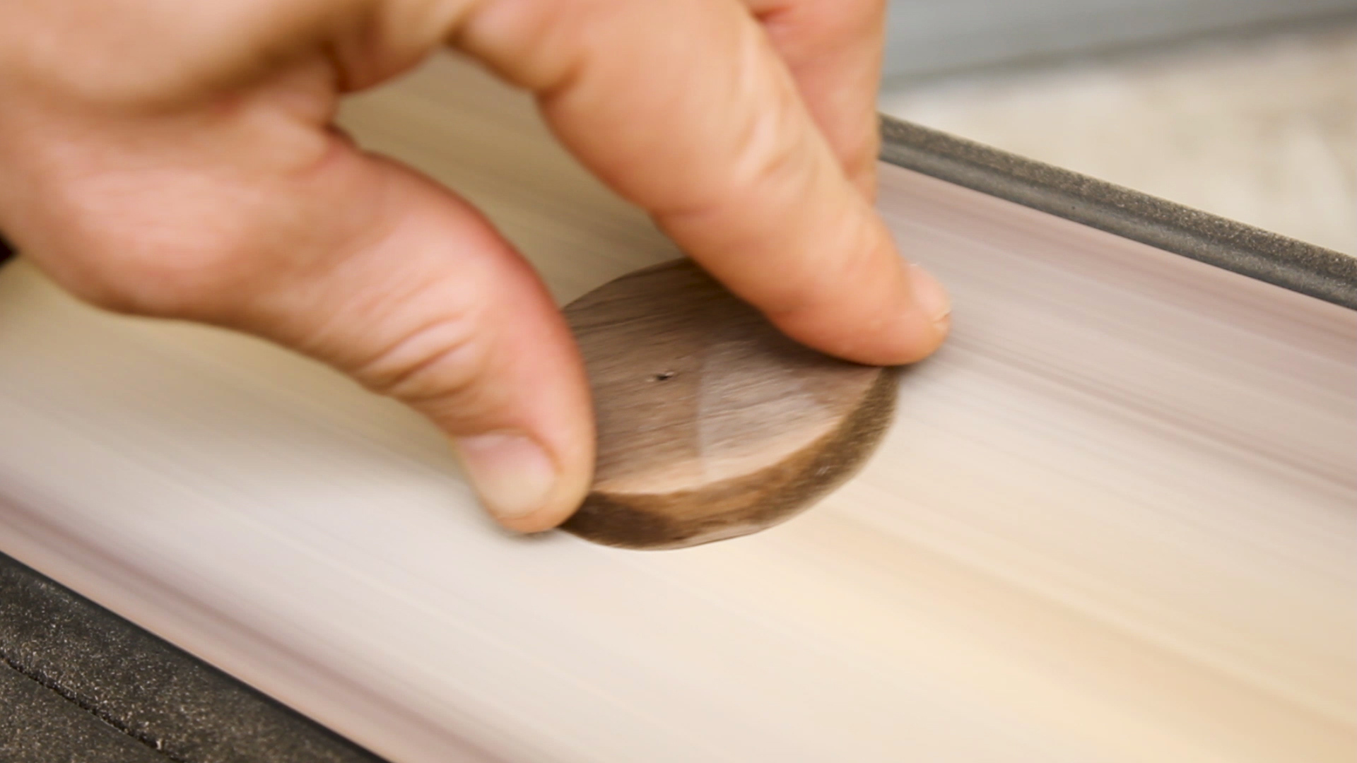
Pictures 5 show me spinning the drill at high speed against the moving belt sander, resulting in a (mostly) round top. I thought it was a bit clunky though (Picture 6).

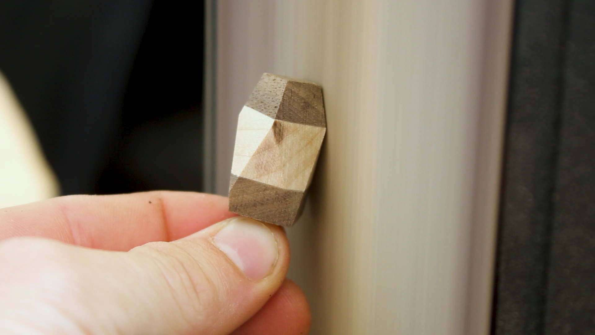
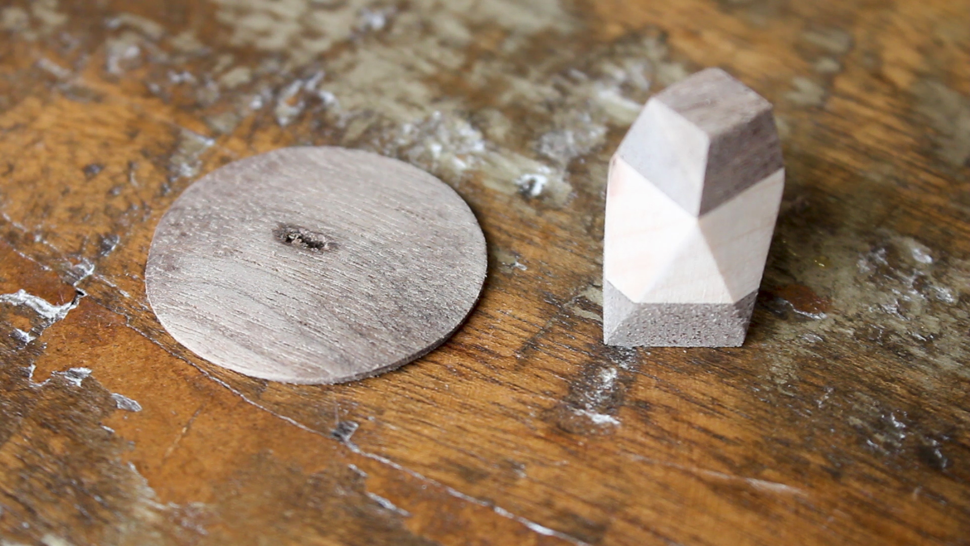
In Pictures 7 - 8, I took the top back to the bench sander and just smoothed out what I felt was a cool geometric shape. No real design in mind, just flattened in a pyramid shape until I thought it looked cool!

I then took the original lid piece and screwed it to one of the scrap pieces of walnut (Picture 1) that I had from earlier (remember I said to save those just incase!).

I then crept up on the circular shape of that same top using the disc sander (Picture 2), and then flattened it out and gave it a bit of a taper (Picture 3) so that it would be flat, very low profile, and fit within the lid top of my tea kettle. Picture 4 shows the final two pieces. I then glued these pieces together and let them sit overnight.

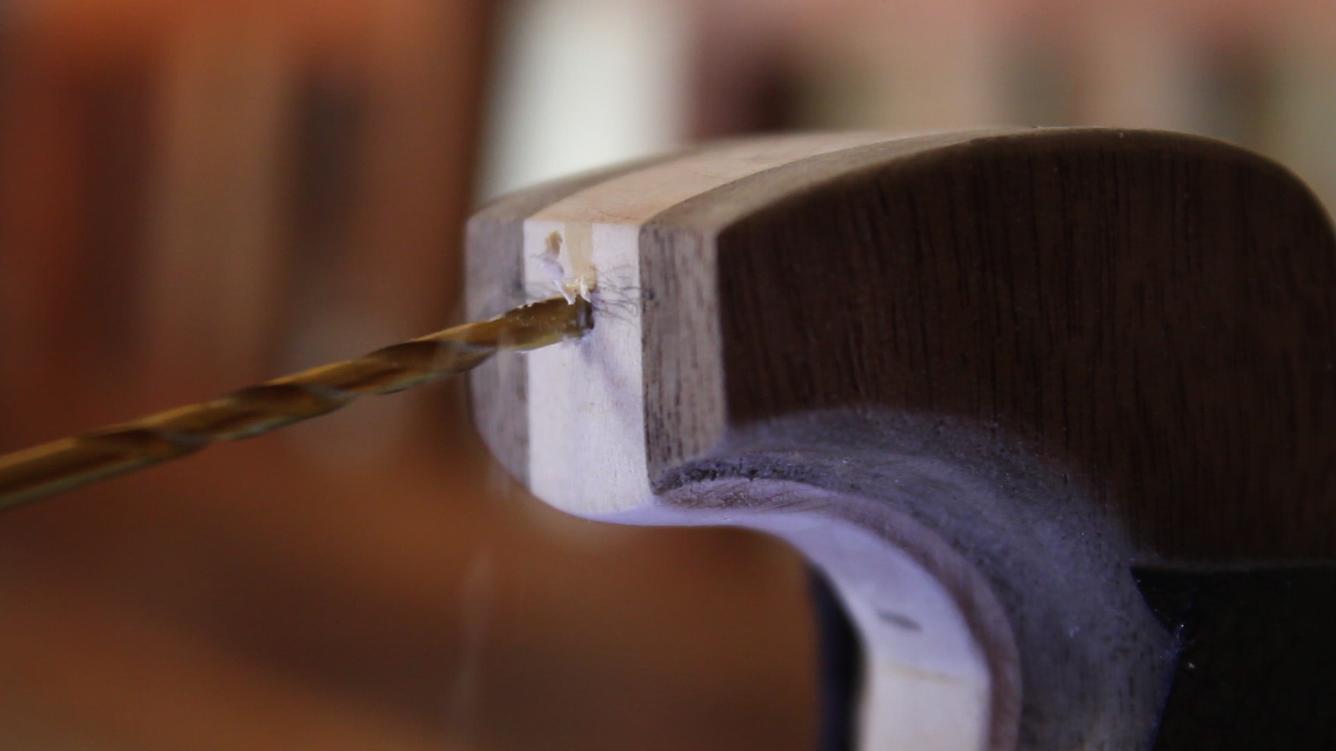
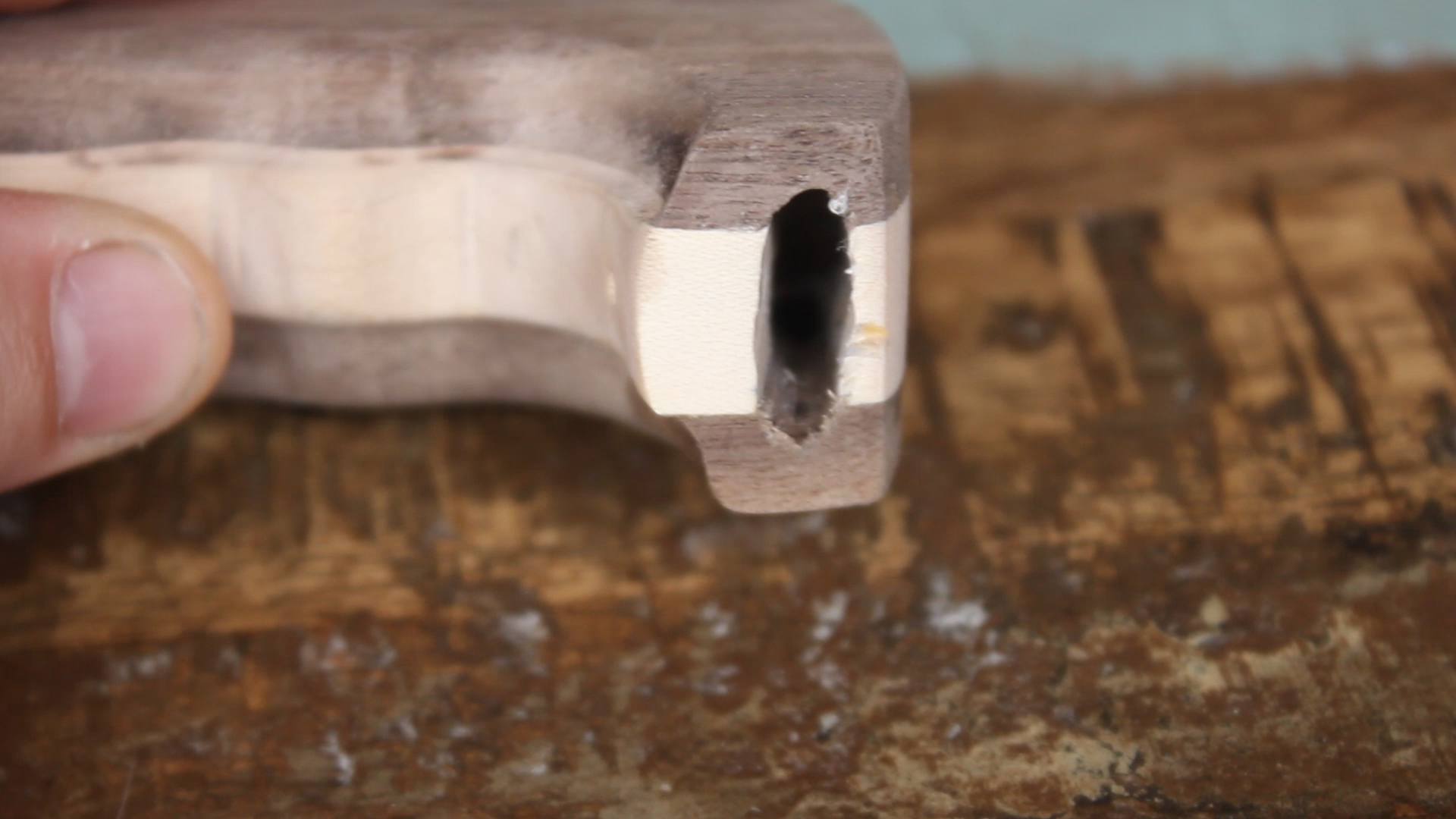
Using my vice again and a small drill bit, I drilled a bunch of holes (Picture 1) to create the larger hole that the tea kettle would slip into (Picture 2). To make this easier, I'd drill small holes, then slowly increase the drill bit size so that they'd all slowly come together to form one large hole, testing the fit in the process. The goal was to make it fit, but make it very snug.

IMAGE 39.jpg

After all was finished, I used some food safe mineral oil to finish the wood, protect is slightly, and bring out the grain. It looked great!

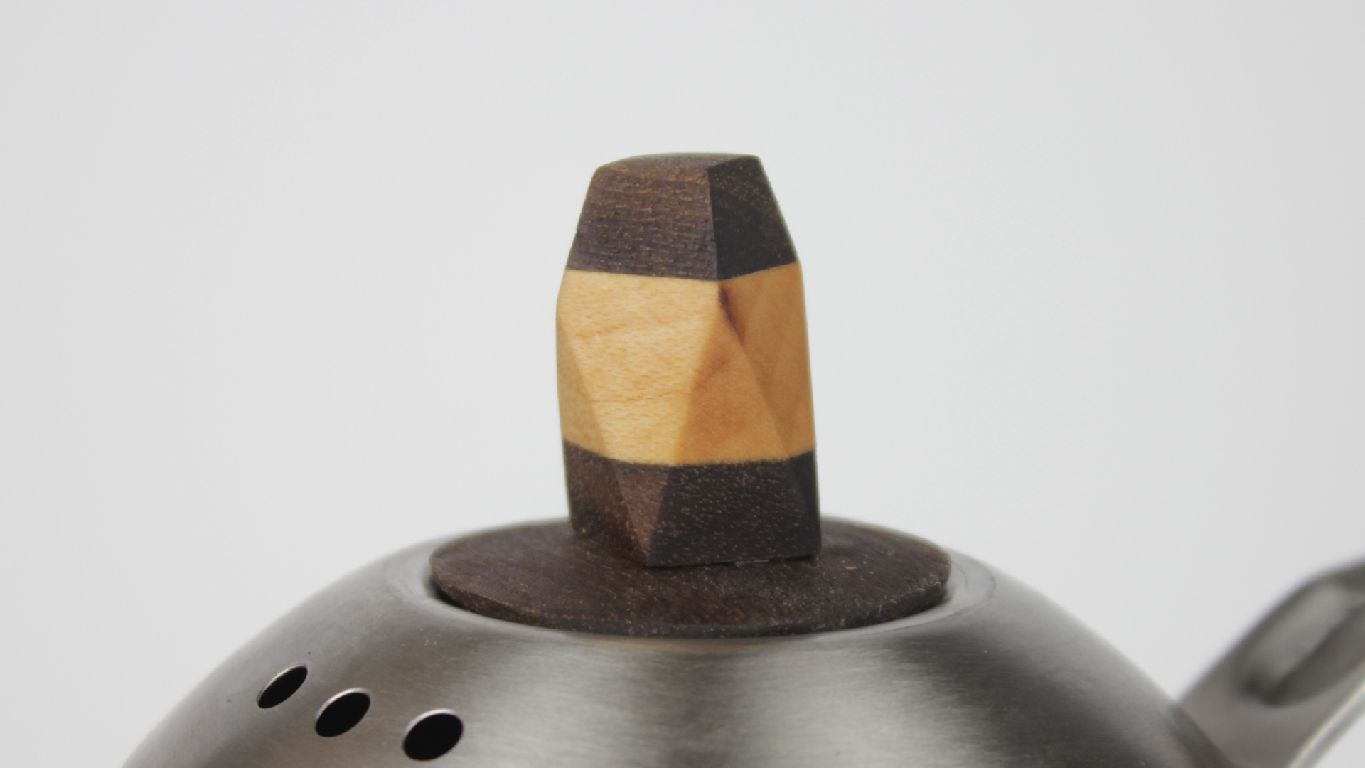
Then, using the hardware from the lid, I installed the new top (Picture 1) - it looks..."okay".

Then, using just pressure and friction, I forced / hammered on the new handle (Picture 2 and 3). It fits very well and doesn't require any hardware. If, for whatever reason, I eventually need to secure it more, I think I'll just use some 5 minute epoxy.

SUB---Intro-WIPE.gif

Thanks for reading!

The above gif shows the transition. Obviously this is a small and subtle overall change, but as a woodworker / maker with a desire to do a bit more "fine" woodworking, I thought that this would be a fun project to tackle in my free time, film in a macro sort of way, as well as share with the maker community for inspiration.

As always, thank you for reading! I would be so grateful if you could please subscribe to my Youtube Channel for future projects. I put out videos every few weeks.

Cheers! 
Zach


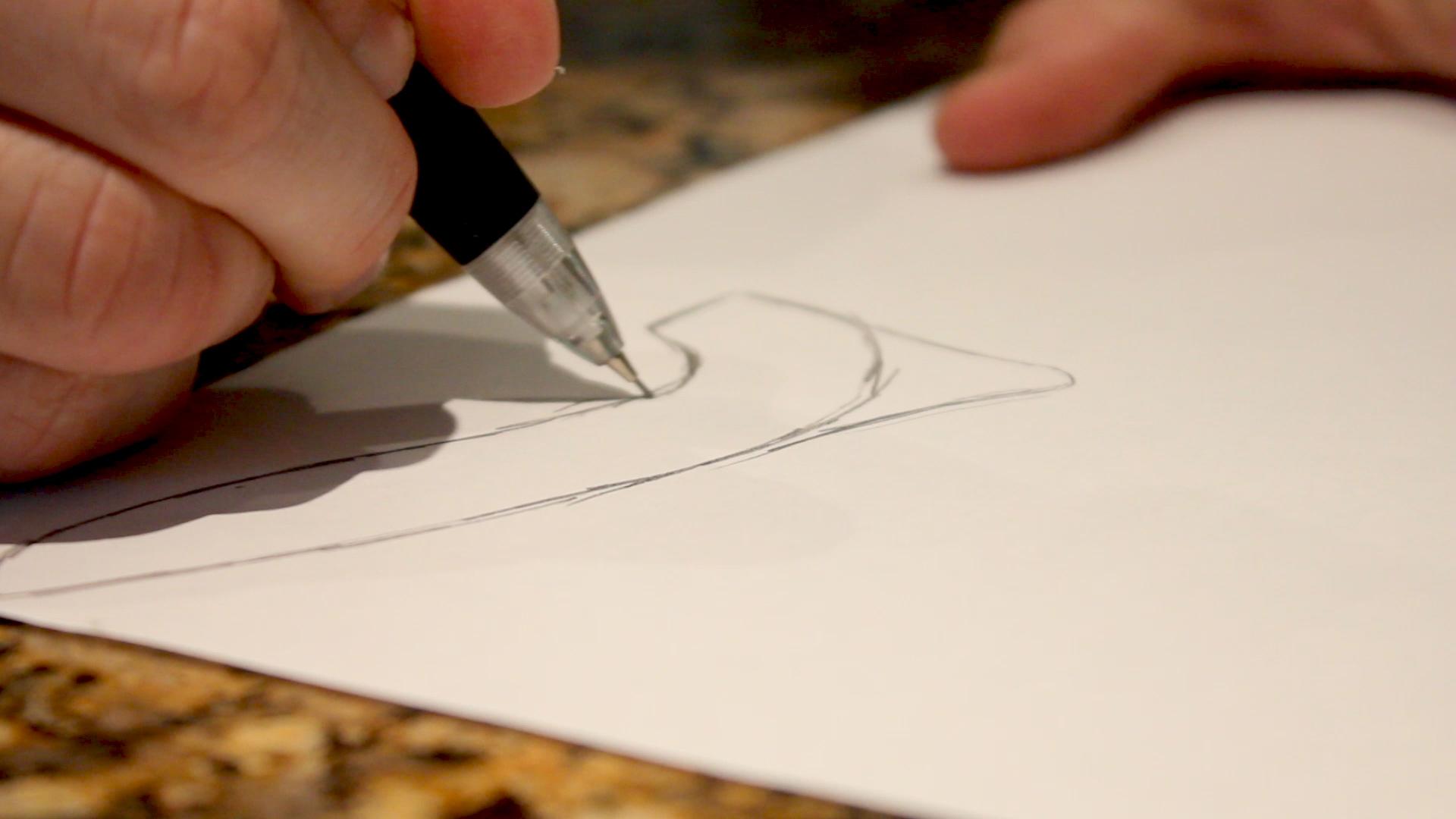
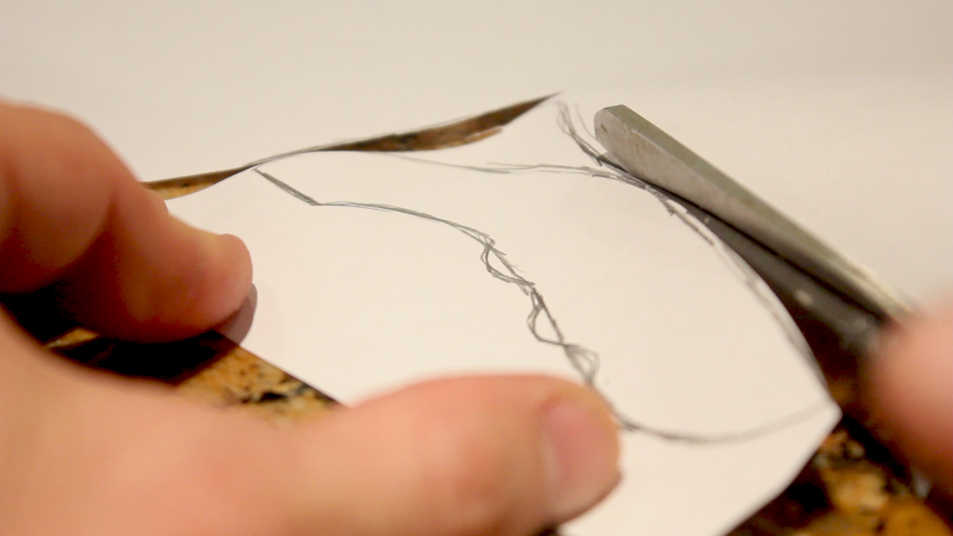
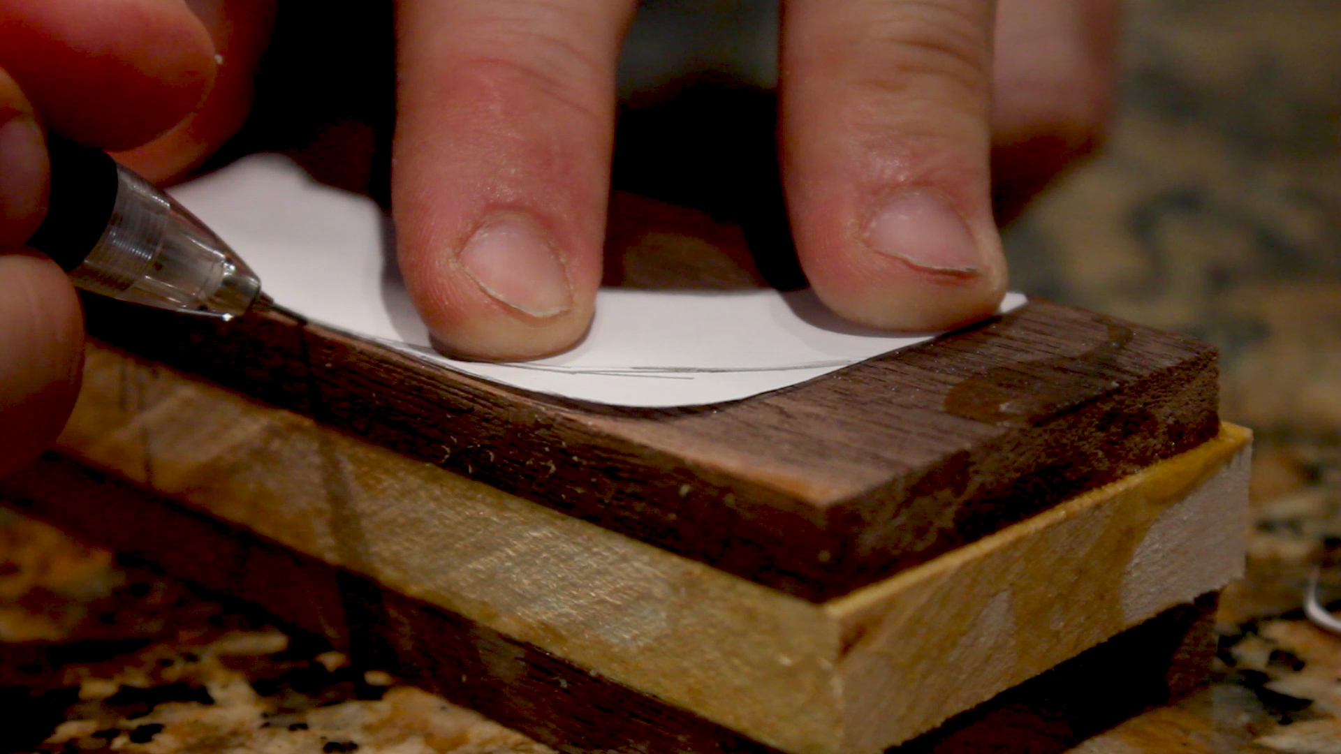
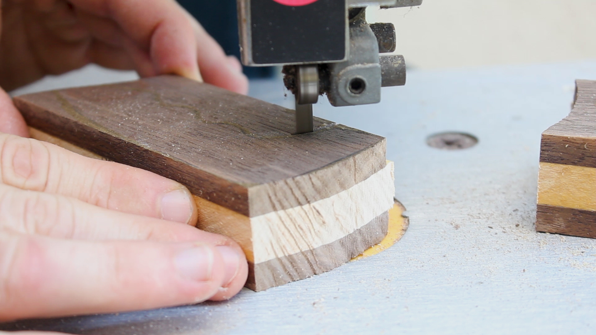
DIY Wooden Hair Comb


Thanks for checking out the full article!
Please Subscribe to our Youtube Channel by clicking here.

My full video of the build is below, followed by detailed instructions with tools, materials, and measurements! 


I always have messy hair. So in this episode, I used some scrap pieces of wood I had to make a comb - it was a fun two day simple project and the result was pretty amazing. 

Shout out to Mike at ModernBuilds for providing the template (which I modified)

MATERIALS
Scrap Hardwoods (IPE, Maple, Mahogany)
TiteBond II Wood Glue
Cutting Board Mineral Oil
Spray Adhesive

Step one was to take my scraps and cut them to length - I cut them all about 12-15 inches depending on the available materials. 

I then cleaned up everything on my stationary belt sander which had a 120 grit belt on it - this would make gluing up much easier and cleaner. 

Once I had my strips, I could glue them up and let them cure overnight. And incase I botched the project the next day, I made a back up blank as well. 

The next day, I could plane it down to my desired thickness. I eye-balled this, but it was maybe 3/8" thick. You can see the two final blanks in the second photo. 

I then cut out and glue on the template to my blank using spray adhesive. I then modified it so my comb would have a handle. 

I then went to cut out my shape. I was super ambitious and thought a coping saw in a vice would be the best route, but I gave up after about 9 seconds of sawing and getting no where and went with my newly purchases (used) bandsaw. It worked great - just take your time with it!

I then went back to my stationary belt sander to round over all of the edges and tape the bristles. Take this slow but also be forceful at the same time. Using a rafter square to press all the bristles down at the same time makes it super easy to give you a nice taper using 120 grit paper. 

I then used a strip of 120 and 220 grit to individually round over all of my bristles on each side and then fine tune all of the outside curves. Was looking good!

Last up, I applied mineral oil to finish the project and bring out the grain and color. I'm sure there are other finishes, but this worked great for my case. 

Then I was done! I tested it out and it worked great and I'm super happy with the result!

TOOLS
RYOBI Stationary Bench Sander
RYOBI Band Saw
Wen 12.5” Thickness Planer
Coping Saw
Vice Clamp
BESSEY Economy 2.5” x 12” Clutch Clamps
Tape Measure
Hand Sanding Sponges (220 and 320 Grit)
Sand Paper (120, 220, 320)

FILM / EDIT EQUIPMENT: 
Canon Rebel EOS T2i
Canon EF-S 18-55mm f/3.5-5.6 IS II Lens
Studio Lighting Equipment
Rode Microphone
Voice Recording

As always, thank you for reading! I would be so grateful if you could please subscribe to my Youtube Channel for future projects. I put out videos every few weeks.

Cheers!

Zach


Making Ovesized Concrete Hex Nut Succulent Planters


Full video of this amazingly fun and versatile project is below which can be found on my Youtube Channel.


The initial steps for this project can be done based on your access to tools.

There is the true maker method of making your own hex nut to mold which requires a few tools that you might not have, or the more simple (and frankly, cheaper and more accessible) way of just purchasing an oversized hex nut to mold and create castings from. I'll show you how to do both as I did in the above video, and will list out the materials I used as well below:

MATERIALS
Oversized Hex Nut (More information on that below)
Scrap Piece 2 x 6 for making your own hex nut
Smooth-On Liquid Rubber for Mold Making + Mixing Bowel
Quikrete 5000 (60lb bag) + WATER
Aquaphor (for greasing molding tray)
Tupperware Container (any size that fits your needs)

SUB---HEX-DRAWING_small.gif

Incase you've never drawn a hex nut, the above gif will show you how to make your own using only a compass and straight edge. A fun trick to know!

After you have designed your hex nut from the previous step, do the following:

Clamp your piece to a secured surface and drill a large hole using a forstner bit (Picture 1). I used the biggest Forstner bit I had, which was 2.125", but if you have something smaller, no big deal.

Next, carefully cut away all sides to your piece using your miter saw (Picture 2). Safety is priority here. Secure your piece to make your cuts as best you can and take it slow.

Last up, you can sand down your edges however you like. I used my stationary belt sander to get it more of a smoothed profile (Picture 3), leaving me with a final Hex Nut to cast (Picture 4). Now, I did not actually cast this one, but I am guessing it would be good to coat it in a non stick surface - maybe a Minwax Polycrylic or even just melted candle wax - so that it doesn't stick to the molding material due to the porous nature of wood.

I purchased this Hex Nut from a company called Grainger Industrial Supply. The dimensions are as such:

Height: 1 15/16"
Width: 3.375" (outside boarder)
Center Hole: 2.125"

and it cost me $18 total. Beyond using it for this project, I have used it mostly as a heavy paper weight to hold things down where a clamp doesn't work - it doesn't replace a clamp, but it does work well to a certain extent as it weighs about 3 pounds

For molding, I'm using a product called Smooth-On (Picture 1). It is a two part mixture that you mix at a 1:1 ratio and sets and hardens over about 6-8 hours.

Before molding, I rubbed my surfaces (Picture 2) with Aquaphor, hoping that it would make it easier to remove the molding after it hardened (spoiler - it did, but not as much as I thought).

I wasn't sure how much molding I'd need, so I started off by using half of the mixture in each container (Picture 3) and combining / mixing in a large bowl for 2 minutes (Picture 4).

I placed the hex nut down in the container, then poured my mixture (Picture 5). 
NOTE - I placed the metal hex nut facing UP in the container before pouring the molding; that way, once the mixture covered the nut and I removed it later on, there would be an opening at the bottom of the mold that I could then use to cast the concrete molding upside down, allowing it to have a bottom. More on that later.

I also vibrated the mold once I cast it to remove air bubbles (Picture 6).

Using pressure, finesse, and an X-Acto blade, careful remove the hex nut from the molding (Pictures 1-4).

Picture 5 shows how wonderful the molding came out!

Now, here is where it is important to cast your blank a certain way. Since we casted it facing up, we ended up with a molding that has a bottom to it. In Picture 6, I am using my X-Acto blade to remove about 1/8" of the center piece of the mold. That way, when you pour concrete in, there will be a ~1/8" space where concrete can fill the entirety of the mold in a single layer, creating a bottom to your planter. Without this, it will just be like your original metal blank.

I have never done this before, so this was trial and error. I'm using Quikrete 5000 for this project as it is about $5 for a 60lb back and was recommended from other videos I watched on the process.

In Pictures 1 - 3 I scoop out, add water, and mix the concrete till it has the consistency of pancake batter. Now, this might be trial and error for you. My advice, error on the side of less water. You really don't need as much as you think, and making it too soupy will result in weakened final moldings that break rather easily.

In Pictures 5 - 6, I pour in, push down, and vibrate out as many air bubbles as I can. As you can see in Picture 5, by cutting away that 1/8" layer in the previous step, the concrete will span the entirety of the hex mold shape and create a base layer to serve as the bottom of the molding.

Two things I want to discuss here.

First, in Picture 1, you can see a broken hex nut. This is for two reasons. One, I pulled my molding out way too early (about 12 hours). I recommend waiting (based on experience), at least 24 hours for the concrete to set and cure.

Second, as discussed in the previous step, my mix had too much water, and resulted in a weaker overall final product. I don't believe these would have ever held up regardless of how long I let them cure. To rectify this, I used a piece of chicken wire (you can really use any flexible metal like a paper clip) to create my own mini-rebar (Picture 2).

I then mixed up another batch of concrete, this time using much less water, and cast another mold, pouring about 1/3 of the mixture into the molding, adding the chicken wire (Picture 3), then pouring the rest and doing the whole "vibrate out the air bubbles" method again.

Like I said before, I let this one sit for much longer before trying to remove. About 36 hours to be exact.

Removing these from the molding was a little tricky. My advice, take it slow and hold it up to your ear when doing so. As you squeeze, pull, and flex the mold, you will hear the mold separate itself from the concrete, and slowly it will slip out. Takes about 2 minutes-ish once you get decent at it. Hex nut fresh from the molding is in Picture 1.

The bottoms / bottom corners were a bit rough, so I used some sand paper to hand sand down these edges (Picture 2) to give everything as clean of surfaces as I can. Concrete actually sands away pretty well. You can also use a stationary belt sander to do this if you fancy speeding it up - but I found it can be a little aggressive if you're not careful!

These work awesome as succulent holders, candle moldings (I did my first wax melting / custom candle making session), cool little book-ends, and probably 100 other neat things I haven't considered yet!

TOOLS For Making Your Own Hex Nut (If you have the tools...)
Compass
RYOBI Power Drill
RYOBI 10 in. Sliding Compound Miter Saw
RYOBI Miter Saw Stand
BESSEY Economy 2.5” x 12” Clutch Clamps
RYOBI Stationary Bench Sander
Forstner Bit (2.125”)

TOOLS for Molding / Finishing (Needed regardless)
Any tool that can vibrate (I used my RYOBI Multi-Tool)
X-Acto Blade (for trimming mold)
Cup / Mixing Apparatus for Concrete
Hand Sanding Sponges  

MY FILM / AUDIO EQUIPMENT
Canon Rebel EOS T2i
Canon EF-S 18-55mm f/3.5-5.6 IS II Lens
Studio Lighting Equipment
H4N Zoom (VO Recording)

As always, thank you for reading! I would be so grateful if you could please subscribe to my Youtube Channel for future projects.

I put out videos every few weeks.

Cheers! 
Zach


Industrial Hardware Shelves


THANKS FOR CHECKING OUT THE FULL ARTICLE!
I'D AlSO RECOMMEND YOU CHECK OUT MY YOUTUBE CHANNEL BY CLICKING HERE.

This was the second DIY Project I ever took on - nearly two years ago - it was low on the woodworking skill but high on the design / pre-planning skills. I wanted to share it here as I probably get the most compliments on these shelves in my apartment of anything I have built...which maybe means I built other things that were a lot less cool!

I saw a picture online (can't find that anymore) of shelves that I liked from Restoration Hardware - they were $300+. That's a big "hell no" for me. Time to build my own.

Quick tape layout for measurement. Shelves will be slightly smaller, but you get the idea.

Started off by taking a trip to Home Depot. I was working off of only one reference image I had found and with zero direction and very little building experience...I bought what I believed was exactly what I needed. I also spent a good 45 minutes in the galvanized pipe aisle testing out combinations, double checking which parts I bought...

Side Note - I can't believe I got everything in one trip from Home Depot.

Wood / Stain Materials
1 x 1" x 6" x 4' Whitewood (Cut into 2 x 15", 1 x 18")
Ash Woodstain
Toggle Bolt Screws (to mount to drywall)

Pipe Pieces (All 3/4" Galvanized)
6 x 0" (just to serve as connectors)
4 x 1"
4 x 3"
2 x 4"
2 x 7"
2 x 12"

Pipe Connectors
4 x Pipe Flanges
2 x Tips / Nipples
6 x Elbows
4 x T Pieces
5 x Pipe Connectors

Pipes Imgur PSD Diagram.jpg

Here is a grid of how everything comes together - I color coded pieces in the picture and below to help you map our and references things - all pipe pieces 3" and above are White.

Pipe Pieces (All 3/4" Galvanized)
6 x 0" (lime green)
4 x 1" (red)
4 x 3" (white)
2 x 4" (white)
2 x 7" (white)
2 x 12" (white)

Pipe Connectors
4 x Pipe Flanges (Green / Yellow)
2 x Tips / Nipples (Blue)
6 x Elbows (Teal)
4 x T Pieces (Magenta / Pink)
5 x Pipe Connectors (Orange0

You need to drill six total holes at 1" wide in order to connect everything. The best part about these pipes is you can always tighten them one extra turn incase the holes you drilled are slightly off - they tighten very well and are very sturdy.

Picture 1 is the pipe assembly of the middle section - I assembled my pieces beforehand as it was helpful in measuring out exactly where the holes needed drilling.

Picture 2 is me measuring out the two outside sections with the pipe pieces

Picture 3 shows the final drilled holes of each section.

Stain your wood whatever color(s) you want! I chose a darker ash color, but you could choose to paint, or add watery paint for hints of color and then stain - so many options! I did two coats with no pre-stain conditioner and it was all good!

I began assembling my various other pieces.

Picture 1 shows the two outside pieces (left side), and the middle piece (right side)

You can see how using the 0" pieces on the ends (Picture 2) allow you to then pass your pipes through the holes to connect things without using any glue or screws.

More Assembly. I took all of my assembled sections and inserted the wood via the holes I drilled.

Picture 1 shows the middle piece being inserted.

Picture 2 shows me combining the top outside piece to the middle one.

Picture 3 shows them fully assembled, including the pipe flange pieces I'd use to connect the piece to walls.

TOOLS
RYOBI Circular Saw: http://amzn.to/2q1l5wn
RYOBI Power Drill: http://amzn.to/2q1l5wn
RYOBI Drill Bit Set: http://amzn.to/2oKKWXi
RYOBI Cordless Orbital Sander: http://amzn.to/2oICOaP
Tape Measure

If you want to know any materials, tools, or have any general questions answered, you can check out the second step or contact me via my website, thecuttingbored.com and I would be happy to do answer them.

As always, thank you for reading! I would be so grateful if you could please subscribe to my Youtube Channel for future projects.

I put out videos every few weeks.

Cheers! 
Zach


DIY Router Sled


THANKS FOR CHECKING OUT THE FULL ARTICLE! 

Full video build is below, followed by detailed instructions with tools and measurements! You can subscribe to our YouTube channel by clicking here!

I have a 13" Ridgid thickness planer that is a tank. However, I can only plane up to that width, and it is unsafe to do anything end grain (in my personal opinion), so I have, for a long time, wanted to build my own jig. I chose to use MDF wood knowing that it was already very smooth, very easy to cut and rip into the right dimensions, and is quite cheap.

Also, I stand by this design - it worked incredibly well for me on my first go around and I cannot wait to use it again.

MATERIALS
2 x 2' x 4' Pieces of MDF Wood (1/2" thick)
1 5/8" Wood Screws

TOOLS
RYOBI Table Saw: http://amzn.to/2h6ZQc4
RYOBI Power Drill: http://amzn.to/2q1l5wn
RYOBI 10 in. Sliding Compound Miter Saw: http://amzn.to/2q1klHw
RYOBI Miter Saw Stand: http://amzn.to/2p1072e
RYOBI Plunge Router: http://amzn.to/2p15eiC
1” Dado Bit: http://amzn.to/2eR6tOO
RYOBI Drill Bit Set: http://amzn.to/2oKKWXi
BESSEY 2.5” x 12” Clamps: http://amzn.to/2oIJGVy

AUDIO / VISUAL EQUIPMENT
Canon Rebel EOS T2i: http://amzn.to/2pwwlDI
Canon EF-S 18-55mm f/3.5-5.6 IS II Lens: http://amzn.to/2pwmuhi
Rode Microphone: http://amzn.to/2oIExg3
Studio Lighting Equipment: http://amzn.to/2rtrkg0
Adobe Premiere (Editorial): http://amzn.to/2oIXKhE

Here is a link to a SketchUp model of the entire build for purchase.

My build video uses uses a single piece of 4' x 4' x .5" MDF; this model using a single piece of 4' x 4' x .75" MDF as it will be more rigid, flat, and sturdy. Good luck!

I'd love to hear if you build this, so make sure you send me a picture or tag me in your build @workshopedits on IG. Cheers!

Below is the full design of my build in 2D if you are uncomfortable with SketchUp (remember - SketchUp is free to use online so don't be afraid to learn to use the software!). It took me 2 hours of videos and hands on use to get the feel for how it works, the shortcuts, etc. It’s incredible. Go. Learn. It.

I purchased my MDF material at Orchard Supply Hardware in SoCal, where they sell it in 2' x 4' sections for $8 each. EDIT in 2020 - RIP to OSH - you were incredible. You can still get the same wonderful MDF at Home Depot, Lowest, etc., but in 4' x 8' sheets

You can use the large amount of excess to build additional jigs or just build a larger sled if you'd like!

Picture 1 shows the cuts needed for the sled base
Picture 2 shows the cuts needed for the sled.

My design leveraged the original size of my MDF. So, if you want to design the same one, then you don't need to make any cuts. High five yourself because you just saved yourself 3 minutes.

I cut two strips from the second piece of MDF all the way through at 2.5" wide. I chose this as it would translate to me being able to plane surfaces up to that thickness. I can always cut larger strips to make the sled higher if needed for very cheap.

Next, I measured the width of the base of my router plate - this will change based on what router you have. Mine was a little over 5.5". I went ahead and added 1/4" - 1/8" to that width, and then ripped down another strip of MDF from the same piece that would later become the floor of my sled and the outside guides.

Lastly, I ripped two more strips, 3 inches wide to serve as the walls of my sled. Given that the sled itself will be about 25" wide, you'll need to rip two strips as cutting one single strip and then cutting in half will not yield you enough material (48" / 2 = 24" < 25"). #Math

To begin the assembly, I clamped a single base wall to the edge of my large base piece, making sure everything was as flush and straight as can be (Pic 1), pre drilled holes for the screws (Pic 2), then screwed in and attached the sled base wall (Pic 3).

Picture 4 shows the final result. I then repeated for my other wall and was finished with the base

NOTE - You must pre drill with MDF as it'll split very easily otherwise.

The goal of the sled is to hang over the railings of your base by the same width as your material. My sled is 24" wide, so I measured out, using scrap pieces of MDF, the exact width of the bottom of my sled. This came out to be 25' (24" sled width + 2 x 1/2" material).

I then made the cuts (Pic 2) on my Miter Saw. I then measured our the sled sides to be the exact same with as the sled bottom (Pic 3) and cut to length (Pic 4). Then, using left over pieces from cutting my sled bottom (from Pic 2), I cut two pieces at 2" wide to serve as the guides for the sled against the walls (Pic 5). I also decided to add 45° angles to the sled walls (Pic 6), which has no function, I just thought it looked better aesthetically.

Picture 7 shows all of the final cuts (sled bottom, sled sides x 2, sled guides x 2)

Clamp our Sled Wall pieces to the outside of your sled bottom piece (Pic 1). Double check that your router will fit comfortably but still tightly in between.

Pre-drill holes (Pic 2) and screw in (Pic 3) your wood screws like you did with the sled base to assemble the sled. Repeat this process for the second wall on the other side.

Finally, clamp on your guides underneath the ends of the sled base (Pic 4), pre-drill holes again (Pic 5), and screw in screws (Pic 6) to attach the guide. Repeat this process for second guide on the other side.

Double check your sled fits and slides tightly but freely on your sled base. If you are careful with measurements and make clean cuts, this shouldn't be an issue at all!

Using your Plunge Router and a Dado Bit (Pic 1), plunge your router into your sled to begin routing a groove (Pic 2). Once you have made multiple passes and cut all of the way through, you should end up with a groove (Pic 3) that you can now pass your dado bit through and surface any piece of wood, etc. that you place under the sled.

NOTE - You have the freedom to route this hole as wide as you'd like, but be careful not to do it too wide as you'll hit your sled base walls. Also, because your router will have a bit of wiggle room, you'll want to make passes with your router base plate up against both walls so the hole is clean, consistent, and slightly larger than your actual dado bit width.

Below is the full video of me using it for the first time on a set of Walnut Butcher Block Bedside Tables I was making.

I am so thrilled with how well it works, and it will work for ANY type of wood material you put underneath, all you need to do is make sure the piece is secured and shimmed properly so that you begin with as flat and stable of a surface as you can (I held it with weights, but you can look into your own solutions that work for you!).

The best part is, between the tools you need for the sled, and the materials, it will still be about half (or less) the price of a standard thickness planer, which many people can't afford and will be limited by anyways.

If you want to know any materials, tools, or have any general questions answered, you can check out the second step or contact me via my website, thecuttingbored.com and I would be happy to do answer them.

As always, thank you for reading! I would be so grateful if you could please subscribe to my Youtube Channel for future projects.

I put out videos every few weeks.

Cheers! 
Zach


Simple Floating Book Shelves


Thanks for checking out the full article! 

Full video build is below, followed by detailed instructions with tools and measurements! You can subscribe to our YouTube channel by clicking here!

We have a gallery wall in our apartment, and my fiance wanted a set of floating shelves to put her books on. Simple and cheap project, many ways to do it, and a great final result for the average DIYer

MATERIALS
1 x 1" x 8" x 8' Whitewood
TiteBond II Wood Glue
Minwax Golden Oak
1” Brad Nails
Frog Tape
Angle Bracket Hardware (your choice!)

I built these shelves two ways, with different tools, to make it easier for the average DIYer. 

Method 1
Miter Saw + Table Saw

For the project, I'm just using a 1x8 piece (8 feet long), so I measured out 11.5 inch pieces and cut them to length on my miter saw, resulting in a set of four pieces (Pic 3). I then set my table saw blade to 45° and ran each piece through the saw to give each edge a clean mitered corner. 

The reason I didn't do this all on my miter saw is that it does not cut 100% straight, which is then amplified as I do miter/beveled cut. 

Method 2
Circular Saw + Straight edge

If you only have a circular saw, you can carefully mark / measure out your lines, set your saw blade to 45°, and cut then rotate and repeat the cut to give you the exact same piece. Take your time, be careful with your measurements, and it will be great!

I used the "masking tape" method to glue these up. However, given that it was about 107° out that day, the tape wouldn't stick to my material, and although it kind of worked, it didn't really. So, after lining up the pieces on the tape and applying glue, I folded them up, and then used brad nails to hold them in place. If I could go back, I'd just clamp all four sides and the joints would be clean, strong, and not require any nails. 

As such, I did use brad nails as it expedited my process as I had limited clamps at the time of the build. 

Once it dries, you're left with a sweet looking box, like this

IMAGE 14.jpg

Next up, I sanded down the edges of the boards using an orbital sander at 80 grit followed by hand sanding at 120 - no splinters!

Last up, I stained my shelves using Minwax's Summer Oak stain - no pre-conditioner or anything. This stain in particular soaks in well, and I'm always satisfied with the result. 

I'll be using the below hardware to hang my shelves. The hardware on the left is for mounting to drywall (anchor and screw), and the right is for attaching to the wall and the shelf. 

Then, I did the following to hang my shelves:

  • Place my shelf where I thought it would look good
  • Mark and measure out the spaces where your holes will go, using a level to make sure things...are level
  • Pre drill holes based on your screw size
  • Lightly hammer in your anchors
  • Drill in and attach your angle brackets
  • Mark the location of where your shelves will attach to the brackets
  • Pre drill holes for the screws
  • Hang up and hand screw in the screws

And then they were hung! And I put them to use!

Thanks for reading! I hope you're inspired to go build your own. Remember, you don't need much to make it happen!

TOOLS
RYOBI 10 in. Sliding Compound Miter Saw
RYOBI Miter Saw Stand
RYOBI Table Saw
RYOBI Circular Saw
RYOBI Power Drill
RYOBI Cordless Orbital Sander (80 Grit)
12” Rafter Square
RYOBI Drill Bit Set
Level (24’)
Hammer
Hand Sanding Sponges (120 Grit)

FILM / EDIT EQUIPMENT: 
Canon Rebel EOS T2i:  
Canon EF-S 18-55mm f/3.5-5.6 IS II Lens
Rode Microphone
Voice Recording
Adobe Premiere (Editorial)

LIGHTING
Studio Lighting Equipment

 I would be so grateful if you could please subscribe to my new Youtube Channel for future projects. I put out videos every two weeks.

Cheers!

Zach


Double Barn Doors


Thanks for checking out the full article! Please Subscribe to our Youtube Channel by clicking here.

My full video of the build is below, followed by detailed instructions with tools, materials, and measurements! 

My friend knew I liked to build, film, blog, and share. He wanted two barn doors, so I was off to create my first project. He gave me all of the important measurements (door height, hardware he ordered, style references for doors, and color preferences). 

MATERIALS
10 x 2" x 8" x 8' Douglas Fir (Kiln Dried)
2 x 2" x 4" x 8' Douglas Fir (Kiln Dried)
75 x 1/2" Wooden Dowels
TiteBond II Wood Glue
Frog Tape
Minwax Classic Grey
Minwax Ebony
Minwax Pre-Stain Conditioner
Barndoor Hardware

Douglas Fir lumber is rather rough, so I started off by planing all of my pieces down. Between the amount of lumber I planed and the fact that my planer is on the ground, I was actually in quite a bit of pain by the end of it. I did about 3-4 passes on each side of the lumber to bring it to a nicer, flat surface. Then, I cut all of my pieces to length. 

CUTS:
20 x 2" x 8" x 40"
10 x 2" x 8" x 40"

It might be difficult to tell from picture three, but the design of each of my doors was as such:

1 x 2" x 8" x 40"
1 x 2" x 8" x 40"
8 x 2" x 8" x 40"
1 x 2" x 8" x 40"
1 x 2" x 8" x 40"

to make a door roughly 82" high (based on the door heigh I needed for this specific project), and it came out looking pretty sweet!

By the way, this project took me a lot longer than expected, with the obvious reason being that I literally needed to do everything twice as I was making two doors. If you're just making one door, things will move a lot faster!

After laying out all of my cuts and arranging them how I liked them, I labeled each piece so that I could put them back in order when I glued them up. 

After I labeled my pieces, I used my large T Square to mark up locations for dowels. This was actually quite easy, just make sure that your pieces are squared up before you make any markings and don't get careless and knock your pieces out of whack while you're measuring!

Then, I used my Rockler Dowel Jig to drill three dowels in each piece. These were necessary for this project given the overall weight of each door and the need for strength between each joint. This jig is quite easy to use as well - you simply line up the center line of the plexiglass with your pencilled marking, clamp it to your piece, and use the associated drill bit to drill your holes to the depth of your choosing (this will be based on the length of the fluted dowels you purchase). 

After each piece was drilled, I used frog or masking tape to tape off the ends of each of my pieces. This was more of an experiment than anything (and actually quite time consuming), but I wanted to see how much this would help me on the clean up side of things. Spoiler - it helped a lot, but probably took equal time to tape up that I would have spent cleaning up glue squeeze out. 

The next part was relatively straight forward. I lined up all of my pieces, applied a large amount of glue to both the surfaces as well as the dowel holes, hammered in my glued up fluted dowels, and then lined everything up and clamped things together to dry overnight. 

Few tips here:

  • Don't try to glue up too much at once; part of me regrets doing the whole thing at once just because of the stress it added to the project
  • I used 10' long pipes for my pipe clamps, which I figured might sag in the middle due to stress, so I used scrap pieces of wood to support it
  • Make sure you have something to clamp on top to counter the clamp stress from the bottom (I didn't have enough clamps, so I used about 150 pounds in weight which worked great. 
  • Dowels kept everything lined up well, so definitely recommend using them both for strength and for accuracy
  • Give it 12 hours to dry; this style of door is heavy and the joint need times to cure and settle

As you can see from the picture, the tape was very helpful in catching 95% of the glue squeeze out. I don't regret attempting this method at all!

I then used a flap disk and my angle grinder to simultaneously remove glue but also add a slight "saw-milled" look to the wood. It doesn't show so much in photos, but it gives the barn doors a more weathered/rustic look. I then went over those rough marks with a hand sanding block at 120 just so it would feel smooth overall to the touch. 

Using an air compressor to clean off all of your surfaces is very effective before staining. 

My buddy wanted charcoal grey doors, which Minwax does not make. So, to make this happen, I combined 3 parts Classic Grey and 1 part Ebony to make a darker mix. I used a pre-stain conditioner for these doors as well. The second picture shows the difference between non-conditioned wood (left) and conditioned wood (right). Quite the difference actually!

The conditioner process is very simple. Just apply a solid coat to all surfaces, let dry for at least 15 minutes but no longer than 2 hours, and then apply your stain. I did one coat of conditioner as recommended and then one coat of my mixed stain to all surfaces of my doors. 

Attaching barn door hardware is actually quite simple. Note, all orders will undoubtedly come with very detailed directions, measurements, and steps to install. For this article, I'll just tell you what I did specific to my hardware. 

The first picture shows the main track wheel piece. The second picture shows the components for attaching (a hex bolt, washer, and nut). My screws were not long enough to go through my doors, so the directions recommended doing a counter sink method for this. 

To do this, I did the following:

  • Based on the directions, mark the center points of your two holes (I believe mine were 1.25" and 4" from the top and 2.875" in from the sides)
  • Pre drill a 1/8" pilot hole on the side that the track pieces will go on
  • Flip the door over and drill a 1" counter sunk hole using a spade bit
  • Drill a 3/8" final hole to accompany the hex bolt
  • Drop the washer in the counter sunk hole, twist in the hex bolt using your fingers and a ratchet wrench, and tighten everything using a regular wrench on the other side. Make sure as you tighten things that your hangars stay perpendicular to the top of your door using a rafter square

Next, time to hang your tracks. My tracks came with pre-drilled holes which I recommend, but if your studs do not line up with those holes, then you'll need to drill new ones which is a bit of a hassle. Nonetheless, the last thing you want is your doors to come crashing down, so do this properly!

I located the studs in my walls, found the proper height to drill my pilot holes based on the height of my door, and drilled into my walls. I used 2 x 6' tracks for this project, and each track had four total holes to connect to the walls using a large lag bolt, a washer, and an adjustable spacer which proved very handy. The other method for hanging tracks easily and so you can avoid having to find studs each time is to use an additional piece of wood that goes in between the track and wall. This piece will be drill into all of your studs for support, and then you can simply just drill in your track based on the pre-drilled holes without needing to locate studs for each one and/or drill new holes to fit your space. I didn't have this luxury but I managed.

I recommend getting a drill bit for this, as hand cranking everything in was exhausting. Use a level to make sure everything stays parallel, and repeat the process if necessary for second track. 

Also, you'll want to install the end stops at this point before attaching your lag bolts to the walls as those will sit in between the track and your lag bolt end. 

After i had both of my tracks up, parallel, and with the stops attached on each end, I could attach my doors. You'll notice there are special locks on these doors. For the sake of this article and my sanity, I will not go into detail about the nor will I recommend using them. Barn doors aren't meant to be locked in my opinion!

Once my doors were on the tracks, I could install the door protector that prevented them from popping off their tracks if hit too hard. Simple process and very effective. There is also a floor guide that needs to be installed to help properly "plum" your doors, but this required additional epoxy that I did not have at the time so I do not have documentation of it. The reason I needed epoxy was because I could not drill into the floor. 

After that, I was finished. The build of these doors was quite fun and straight forward. Hanging complicated barn door hardware, by yourself, for the first time, and with minimal tools is quite complicated, especially when you have to do it twice but make it perfectly accurate. I look forward to doing this again in the future with a partner to help and hopefully with just one door and no complicated add ons. 

Final doors in their new home. Ignore the locks that are not quite finished (long story short, the directions suck and I drilled holes at the wrong depth, meaning that I need to find cool pieces of steal to cover the holes, which will actually look awesome when added on!

TOOLS
Wen 12.5” Thickness Planer
RYOBI 10 in. Sliding Compound Miter Saw
RYOBI Miter Saw Stand
RYOBI Cordless Orbital Sander
RYOBI Power Drill
RYOBI Drill Bit Set
ROCKLER Dowelling Jig
Rubber Mallet
MAKITA Paddle Switch 4.5” Angle Grinder
Flap Discs
BESSEY Economy 2.5” x 24” Clutch Clamps
BESSEY H Style Pipe Clamps
12” Rafter Square
Level (24’)


DIY Wooden Beer Mug (No Lathe)


Thanks for checking out the full article!
Please Subscribe to our Youtube Channel by clicking here.

My full video of the build is below, followed by detailed instructions with tools, materials, and measurements! 

My friend had two old shelves (wood species unknown at this point) that he didn't want. I thought it would be fun to convert one of them into a wooden beer mug. So I did!

MATERIALS
Hardwood of your choice (about 2-3 board feet, 4/4 stock)
TiteBond II Wood Glue
Mineral Oil

The wood I had acquired was previously finished with some type of oil, so the first steps were to remove that finish so that the wood would be returned to useable lumber and glue-able! I only removed what I needed to keep as much thickness as possible. The result was wood about .70" thick. 

Next I could rip my pieces into strips at 3.5", then cut those 3.5" strips into squares. I think I ended up cutting 9 total squares. I also cut four pieces at 4.5" long that would later become the handles. I then glued things up. 

You can see how I glued up all the squares to form the "mug" blank, and the longer pieces to form handle blanks. NOTE - I glued up two sets of handle blanks (two pieces each), incase I messed up later on. These are not four piece glued together, they are two pieces glued together, just clamped up together. I was careful to make sure the grain of my wood all ran the same direction as well for the "future mug" blank. 

The next step was to find the center using two diagonal lines, followed by using a compass to mark out two circles. Since I don't have a lathe, I can't turn this piece on the inside and outside. 

Instead, I'll be hollowing it out with a forstner bit, and rounding off the outside using various methods detailed later. My forstner bit is 2.125", so that is the size of my center circle. Then I just measured about .50" outside of that to create a parameter for the outside of the cup. 

Then I spent a good amount of time boring a hole using my power drill. Without a drill press this was a lot of work and probably took me three total Ryobi Batteries to complete. I ended up drilling about 5.5" deep. You can see in the last two photos the depth at which I dug. That is an 8.4 oz. can of soda (for reference), so the cup probably holds 10 oz total. 

This next step can be done many ways. The whole point is just to remove excess material so that it is easier to round out the outside of the mug later on with a belt sander. I chose to use an angle grinder with my ARBORTECH TURBOPlane Blade, but it can also be done as such:

  • Miter'd band saw cuts
  • Miter'd table saw cuts
  • Miter Saw cuts
  • Hand carving tools
  • All belt sanding (takes the longest)

Then, I could move to my stationary belt sander and begin rounding out the edges. I was using 120 grit sand paper at this point which wasn't course enough, so this took longer than expected. 40 or 60 grit would speed things up for you. I was pretty excited at this point with how the grain was starting to look! I also flattened one side to where the handle would eventually be glued to just to have flat clean glueable surfaces. 

Next up was shaping the handle, the design and drawing of which was completely freehanded and not based on anything but the idea that it should look and function like a handle. I then moved to sanding all faces of it, including rounding the interior and exterior edges as well as flattening the ends that would later be attached to the mug. 

I then wetted everything down and gave it one final sanding at 220 and 320 grit. I did this to both smooth it out as well raise the grain on the wood so that when it did get wet eventually, it would remain smooth. 

hen I glued my handle to my mug using Titebond II Again. Only glue here - no screws (obviously!), no joinery. Just apply a solid amount of glue, spread it out, and push and hold it firmly to the mug surface for a few seconds for it to set. Then clamp it up. 

The glue joint, if clamped and tightened properly, would be strong as hell.

he last step was two fold. 

First, I applied mineral oil to finish the cup and bring out the color and grain (looked awesome!). Second step was to take wood glue (food safe and water proof) and rub a few layers of it on the inside of the mug to help protect the interior. 

NOTE - This by no means is the only way to do this, it just made the most sense to me based on what materials I had at my apartment. I'll let you know how the glue sealant holds up...

Then I was finished! Below are final pictures of the mug! I think it is pretty awesome! Grain looks great and the directions of which it runs looks fantastic, the shape is basic but fun looking, and it functions great!


Box Joint Coffee Table


Thanks for checking out the full article!
Please Subscribe to my Youtube Channel by clicking here for future vids!.

My full video of the build is below, followed by detailed instructions with tools, materials, and measurements! 

This faux box joint style is really cool in my opinion. It can be achieved with a bit of good design, focus, and precision, and has very unique results when totally finished. I had built something similar once before and learned a lot in the process, so I was excited to take on another build similar to it but with my past experience in hand. 

MATERIALS
18 x 2" x 3" Framing Lumber*
2" Finish Nails (not totally necessary)
TiteBond II Wood Glue
Dark Walnut Danish Oil
Minwax Clear Finish Polyurethane
 

*Note - This amount of material fits my specific design / dimensions

Step 1 was just to design the whole project. Below are my designs that I worked from:

Screen+Shot+2020-03-20+at+11.39.24+AM.jpg

Here is a free SketchUp model for you to access the exact design of the model incase you're interested!

Top Profile.png

This is my design looking straight down from the top.
Blue cuts are the longest pieces I'd need for my project.
Pink cuts were initially measured out, but would be contingent upon the final width of the wood as the length of the pink piece + the width of the two yellow pieces would need to add up to the length of the blue piece

This is the side profile of the table. You can see that the green leg pieces will be shorter due to the blue pieces extending to the end of the table. The Yellow pieces (not shown here), would be the length of the green pieces + the thickness of the blue piece (if that makes sense)

This is a view from the bottom of the table. The yellow and green pieces did not have a definitive length during design (but were roughly 15 and 12.5 inches, respectively). I will give my final cuts later. 

Bottom Profile with Shelf.png

This is the same view from the bottom, but now includes the bottom shelf that I added in. The brown pieces were the length of my pink pieces + one inch as I was going to be using Dados to hold them in place. more on that later. 

I planed all of my wood down - first to remove the rounded edges, then on each side to give clean surfaces for glue ups.

Removing the rounded edges can be done on a table saw as well, I just hate my table saw and would rather not work unsafely.

The second picture shows the difference between the square side you want and the awful rounded side it started with. 

Now I was selective at the store as to the quality of materials I bought, but once I had everything planed down, I took extra time to sort my wood based on the cleanest surfaces. I chose the best looking ones to surface as my table top parts since that would be the most visible. 

I had planed my wood down to a width of nearly 2.2" - a width I knew was uniform across the board. So in order to make box joints fit properly, I needed leg pieces that were 2.2" different in length as well as top pieces that were 2.2" difference on each side, for a total of 4.4". 

Thus, you can see my table top cuts on the left. I ended up basing my smaller cuts off of a final length of 40" (so 40-2.2-2.2 = 35.6"), as I planned on having my longer pieces a bit long so I could cut them down rather than need extra length I couldn't get. 

My bottom row pieces were 1" longer than the middle width of my table so they could sit comfortably in a half inch dado on each side. 

For my legs, since I went for a table height of 15", my shorter pieces needed to be 2.2' shorter than that, or 12.8" roughly. The final picture shows how I made my cuts. Now in my purchase list, I tell you to buy 18 pieces, but in reality, you can get what you need from 17, but having one back up piece is just a smart idea. 

One little tip here is to cut your 12.8" pieces slightly long so that you don't end up with pieces not quite long enough to form the box joint and reach the bottom of your table. You can always plane them down later, which I chose to do, and did, and it worked great. 

Once I had all of my cuts made, I could begin my glue ups. I did this upside down, so the final table top would be facing downwards. I alternated my pieces (photo) on top of two bar clamps and made sure the cleaner looking surface was facing downwards. 

NOTE - in this first round of glue ups, you will only glue together 13/15 of your pieces for the top. You will save your two final outside blue pieces for a second round of glue ups for later as well as the corresponding green legs.

Above is a glue up trick technique I was taught. Using a Kreg Clamp (Pic 1), I could put glue on one piece, spread it out evenly, squeeze together and line up to make sure the box joint edge went out as far as teh thickness of my leg piece (pic 3), then clamp together across the two pieces to keep them flat and flush (pic 4), and then use a 2" finish nail to hold it in place (pic 5). I then could repeat this process for each piece I glued up. The result was a pretty damn flat glue up without a lot of clean up.  

Image 13.jpg

Clean up as much glue squeeze out as you can once you clamp up everything with a wet rag - makes the finish process so much smoother (no pun intended). 

NOTE AGAIN - you'll only have 13 pieces glue up at this point (see image above). 

I then could repeat the process for my legs, alternating pieces (pic 1 and 2 - the alternating process should be relatively straight forward and fit tightly together), then my other side's legs (pic 3), and then finally my bottom table (pic 4). Again, clean away any glue squeeze out for easy finishing later on. 

Your bottom table (pic 4) will have 13 pieces glued together as well. 

Before final assembly, I finished everything. First, I belt sanded all my surfaces using 40 grit paper which flattened everything nicely.

Next, in order to take down the protrusions (remember I cut my longer pieces .5" long), I used my Turboplane and a flap disk to take them down. This can also be done with a block plane, a belt sander with rough grit, a hand held electric planer, or a flush trim saw. 

I then went over all my surfaces with 80 and 120 grit sand paper on my orbital sander. Looked great!

I then took the opportunity here to square up my leg bottoms using my T Square and a circular saw. My saw didn't cut all the way through, so I made one pass, flipped it over, and cut the other side. If your cut isn't perfect, a belt sander will flatten it out quickly. 

As I said before, I wanted to insert my bottom shelf using dado slots. To do this, I used a half inch dado bit (pic 1) and my plunge router. 

Then, I measured 9 inches down from the top on each side, then used my T Square to trace my lines (pic 2 and 3). I used the width of the wood to then trace a second line (not pictured) so I had my entire dado area marked out. 

Then, using a straight edge, my rafter square, and my router, I made multiple passes to cut out my slot. Pic 5 shows it in action, and Pic 6 shows the final dado slot, which was about .625" deep). I repeated this process on each side, being very VERY precise in all of my measurements before cutting. I had never done this before and was proud of the result. 

Doing a final fit! You can see that the dado is not 100% perfect. That is okay, as you'll be gluing on one outside layer on each side of the table next, which will cover up those imperfections. 

In this next glue up, as mentioned before, you'll add in your outside blue pieces (40.5" long) for the table top on each side, as well as your four green legs (15" long) on each corner. Lastly, you'll add in your final two pink pieces (35.6" long).

I didn't use finish nails here, just clamping pressure. I did, however, use little scrap pieces in certain areas so the clamps did not damage the wood from pressure (see pic 2, bottom middle clamp). 

You'll also note that, as I pointed out in my cuts previously, I made my 12.8" pieces a bit long, resulting in four outside leg pieces that were slightly longer than my middle legs and made for a great little leg design unintentionally. 

also used four small angle brackets with screws to secure the bottom shelf from the underside. This would help keep the top of the shelf flush with the top edge of the dado I had cut.

I applied two coats of Dark Walnut Danish oil 8 hours apart to stain the table. Once it had cured, I applied 4-5 coats of a clear satin polyurethane finish to all of my surfaces, making sure to let it dry thoroughly and sand in between each coat with wet 220 grit sand paper. I find using wet sandpaper with poly finishes helps contain the sanding mess. 


Power-Carved Bench


Thanks for checking out the full article!
Please Subscribe to our Youtube Channel by clicking here.

My full video of the build is below, followed by detailed instructions with tools, materials, and measurements! 

MATERIALS
1 x 2" x 4" x 8' 
3 x 2" x 4" x 10'
1 x 2" x 12" x 10'
1 x 2" x 12" x 12"
TiteBond II Wood Glue
Natural Danish Oil

*Note - All wood is Kiln Dried Douglas Fir

I worked on a really fun table build a few months back in partnership with ArborTech using their ARBORTECH TURBOPlane Blade and it was a blast. They sent me a photo reference of another fun project to tackle with it, so I said why not? The coolest thing about this project is that it is held together purely with glue - no hardware is needed and the results, if done right, are stunning!

I made the following cuts from my rough lumber:

From 2 x 4's
12 x 9"
12 x 10"
4 x 13"
4 x 17"

From 2 x 12's
1 x 31"
1 x 32"
1 x 34"
1 x 50"
2 x 54"

Here is a diagram of how my cuts are broken out incase you need clarification. 

Bench.jpg

Here is a SketchUp 3D Design file for $2 incase you’re interested in designing a modified version and getting into power-carving.

Since I would be laminating all of these pieces together, I needed clean, flat surface. 

I planed down all of my pieces as the edges were slightly rough or cupped and in order to make this type of project work, you'll want your surfaces to be as flat as possible to the glue joints are as flush as can be. 

Tip - If you cut all of your pieces and don't necessarily plane and glue them up in the same day, make sure you store them flat and stacked to avoid cupping or bowing. Also, it is easier for me to make my cuts then plane the wood down versus planing very large pieces and maneuvering them constantly.

This next step is a little tricky but I'll try my best to explain. In order to make the back of the lounge chair on one side, you'll need to cut a series of "L" shaped pieces from your 2 x 12" pieces so that when you laminate them together and eventually carve them out, everything will flow nicely and the edge grain will transition properly to the end grain. 

To do this, I made the above cuts by measuring them out using a T square on my wood carefully and then, using just my circular saw and "plunging" it into the wood, I cut make the cuts. The cuts will extend into the corner of the "L" but that is okay as you'll carve much of this material away anyways. The above diagram shows all of the "L" cuts you'll make. 

NOTE - Do NOT cut the small part of the "L" off - your pieces should look like picture number 4 above. The width of the small part of the "L" should be 5 inches wide. 

Next were glue ups. If you watched the video, this might be a bit more clear, but I'll write it out here for full detail:

Legs
You'll end up making four total legs, each using 3 x 9", 3 x 10", 1 x 13", and 1 x17" pieces (pics 1-3) laminated together

Seat Bench
You'll make one bench seat using 1 x 50" and 2 x 54" pieces laminated together (pic 4). I recommend deep jaw clamps for this so you can make sure your middle is glued together - I used scrap hardwood instead as I don't have deep jaw clamps. 

Lounge Back Rest
You'll use the six "L" shaped pieces laminated together (pic 5). Pieces will be laminated together in order based on their length so it forms a stepping shape.

Once all four legs, your bench seat, and your lounge back rest are formed, you can laminated all of those pieces together as well to form this really cool looking "Glulam" bench. Note - I am limited on clamps, so this was 9 total glue ups over the course of a week to make sure all of my pieces were properly secured and cured over the right length of time.   

Now it was time to shape my piece down to it's final form!

To shape this piece, I am using my ARBORTECH TURBOPlane Blade which is a beast at shaping, contouring, and carving away wood. 

I marked out the rough shape I was aiming for using a sharpie (Pic 1), and then, over the course of four hours, I carved away a large chunk of material from my piece to give it a very sleek look. The TurboPlane is great at carving away wood, and as tricky or intimidating as it might sound, it is very easy to control how much or how little you take away. I carved away material on the legs, back rest, and bench top and bottom to create a flowing curved shape.  

Now, while the TurboPlane carves great, it isn't always easy to carve flat. Often, you're left with gouges, which is where Flap Discs come in handy. I used a 40 grit flap disk, which also removes a lot of material, but is much better at only removing "high points", thus helping you to flatten everything out and begin finessing the curves of your piece. I probably did this for 2 hours after carving. 

Then, it literally started snowing where I was, so I called it quits for the day. I was also pretty wiped. 

Back at home where it was sunny, I went back and removed another 5 pounds or so of material using the TurboPlane as the profile wasn't sleek enough for what I was going for. After following that up with more flap disk smoothing at 40 grit, I moved onto orbital sanding at 80 and 120 grit, followed by hand sanding at 120 and 220 grit. I also did a wet sanding at 220 as this piece was going to see a lot of weather and I wanted the grain to remain smooth if it got moist. 

By the way - how cool does picture 3 look with the edge grain transitioning to end grain?

After final sanding, I used a bit of Minwax Wood Filler to take care of a few gaps I couldn't avoid during the lamination stage and then sanded it down. It looks perfect and you'd never notice there were gaps otherwise. This felt unavoidable as Douglas Fir will undoubtedly cup a little bit in between all of these cuts, planes, and glue ups. 

Last up was finishing, and I did one thick coat of Natural Danish Oil on this piece, which helped preserve the look of the wood while also bringing out the grain. I didn't apply any sort of poly or sealant to it as it will be indoors. I will likely revisit a sealant in a few months once I see how the piece holds up as it will be in the mountains and possibly over-exposed to elements and weather shifts. 

Here is a final carousel for you to check out the transition from various stages until the final form of the bench in picture 5. 

As well as a final photos just to check out! I'll post better photos once it is in its final home. 

So stoked with how this thing came out! It is AWESOME. 

TOOLS
RYOBI Circular Saw
RYOBI 10 in. Sliding Compound Miter Saw
RYOBI Miter Saw Stand
Wen 12.5” Thickness Planer
MAKITA Paddle Switch 4.5” Angle Grinder
ARBORTECH TURBOPlane Blade
Flap Discs
BESSEY Economy 2.5” x 12” Clutch Clamps
BESSEY Economy 2.5” x 24” Clutch Clamps
BESSEY H Style Pipe Clamps
Tape Measure
Hand Sanding Sponges (120 and 220 Grit)
3M Face Shield

FILM / EDIT EQUIPMENT: 
Canon Rebel EOS T2i
Canon EF-S 18-55mm f/3.5-5.6 IS II Lens
Studio Lighting Equipment
Rode Microphone
Voice Recording
Adobe Premiere (Editorial)

As always, thank you for reading! I would be so grateful if you could please subscribe to my new Youtube Channel for future projects. I put out videos every two weeks.

Cheers!

Zach


End Grain Coffee Pour Over Station


Thanks for checking out the full article! 

Full video build is below, followed by detailed instructions with tools and measurements!
You can subscribe to our YouTube channel by clicking here!

This was such a great little project. Scrap hardwood is not easy to come by and is quite pricy when bought, so I wanted to make the most of it. I had the concept for an end grain cutting board project influenced by Homemade-Modern's coffee pour over station design a few months back. Not having the proper tools to do it or the materials, I shelved it until I knew I was ready / skilled enough to pull it off. The time is now!

MATERIALS
African Mahogany Hardwood (About 3 BF of 4/4 Stock at 8.5" long)
TiteBond II Wood Glue
Mineral Oil
Galvanized Pipe (see details below!)
Wood Screws

I started by ripping all of my wood into strips at 1.375" on my Miter Saw with the grain. A table saw works better for this if you're looking to do many cuts, but a Miter Saw with a stop was efficient for the number of cuts I made. 

Next, I grouped my strips into sets of six and laminated them together. My one regret here is not mixing up the pieces into more of a pattern based on the various looks of the end grain. Next time! 

Make sure you use lots of glue and a credit card make it very easy to spread and cover all of the surfaces. 

I then clamped all my sets of 6 to dry overnight. I lined up the ends as much as I could and used a mallet and a scrap piece to keep everything very flat (or as much as I could!)

The next day, I ran my pieces through the planer. The manual recommends to not plane anything shorter than 12 inches, but the key should be to not plane anything shorter than the distance between the two rollers of your planer. Otherwise, it will get caught and I honestly couldn't tell you what kinds of things might happen then. If I had to guess, a black hole will open up and the earth will collapse on itself. So tread lightly. My pieces ere 8.5 inches, so I was set to plane and it all came out great. I then square up the sizes of each piece in preparation for ripping strips again. 

I ripped 25 total strips at 1.5" from my 5 pieces, meaning I could get two boards (one with 12 strips, one with 13).

I laid out my pieces on my clamps, flipped a few pieces to mix up the end grain pattern, and then rotated them 90° in preparation for my end grain glue up. 

Same recommendation as before. Use ample glue, spread it well to cover all of your surfaces, square up your edges with scrap pieces or a mallet, and clamp slowly to avoid slipping. Also, you should clamp from the top to avoid bowing, and you can go back after 10 minutes and wipe off excess glue with a wet rag. 

As hard as I tried, this didn't quite glue up flat. I think my surface was uneven to start. You live and you learn. 

Now there is a ton of controversy in the woodworking community about planing end grain. This being my first project and just unsure of all of the consequences, I chose to use my stationary belt sander to flatten everything. It took quite a bit of time, but worked well and left me with a smooth flat finish on both faces and all of the sides. 

I opted to not use a router to take down my edges. Instead, I could just rotate my piece slowly on the belt sander and they rounded out very nicely. Had I wanted another edge style, I might have chosen the other route. After belt sanding, I switched to orbital sanding at 120, followed by hand sanding at 220, 320, and 400, including a wet sanding at 220. Oil won't raise the grain, but knowing this is a cutting board that will likely get wet quite a bit, I wanted to make sure I did a wet sanding to avoid having the wood rough up down the road. I was so stoked at this point at how this project was coming together. 

I'm using a food safe mineral oil specific for cutting boards for this project. This is definitely the most satisfying part of the build. Seeing the grain pop was a lovely experience. I applied two coats an hour apart and wiped off any excess oil once it had dried. 

My pour over station uses five galvanized pipe pieces including (all 1/2"):

  • Floor Flange
  • 8" Nipple
  • Elbow Fitting
  • 1/2" Nipple
  • Tee Fitting

That all are screwed together and held in place with friction. I'd recommend cleaning your pieces with a degreaser or dish soap (at a minimum) before final assembly. 

Last up, I measured out, marked my drill holes, drilled pilot holes, and screwed in and tightened my pipe flanges to one end of my cutting board. And then I was done! I'd call this first project a success. 

Now all I need to do is buy a funnel for the pour over station!

Really digging this thing!

TOOLS
RYOBI 10 in. Sliding Compound Miter Saw
12” Rafter Square
RYOBI Cordless Orbital Sander
RYOBI Combo Power Tool Kit
RYOBI Drill Bit Set

ROCKLER Bench Cookies (Set of 4)
Wen 12.5” Thickness Planer
BESSEY Economy 2.5” x 24” Clutch Clamps
BESSEY H Style Pipe Clamps
Hand Sanding Sponges (220, 320, and 400 grit)
Rubber Mallet
5-Gallon 4.5 Peak HP Wet Dry Vacuum
Air CompressorShop Vacuum
Screw Driver
Spray Bottle (for wet sanding)

Thanks for reading! I would be so grateful if you could please subscribe to my Youtube Channel for future projects. I put out videos every other week.

Cheers!

Zach